Swingable telescopic balance weight structure for railway crane

A technology for cranes and railways, which is applied in cranes and other directions, can solve the problems that affect the application, the structure of the telescopic arm is small, and the requirement for the inner space of the arm is large, and achieve the effect of ingenious design and simple structure

Active Publication Date: 2014-12-24
WUHAN BRIDGE INDUSTRIAL EQUIPMENT COMPANY LTD
View PDF8 Cites 3 Cited by
  • Summary
  • Abstract
  • Description
  • Claims
  • Application Information

AI Technical Summary

Problems solved by technology

In the existing technology, two schemes are basically used to realize the expansion and contraction of the four-section boom: the first is the structure of the telescopic oil cylinder and the rope row, which requires a large space inside the boom, and the railway crane has very strict requirements on the limit , the structure of the telescopic arm is small, and the type of telescopic oil cylinder plus rope row cannot be applied to the counterweight structure; the second solution is to use a single-cylinder plug-in pin structure, which is more complicated in structure and has higher requirements on the control system
[0004] The telescopic counterweight currently used mainly has two structural forms. The first is that the telescopic counterweight rotates together with the upper turntable. During the rotation, the center of the upper turntable and the center of the telescopic arm always coincide, which meets the anti-overturning effect of the increased lifting moment. However, the counterweight will still affect the normal operation of the adjacent line when working within the range of ±30° along the track; the second method is that the upper and lower turntables are provided on the upper part of the crane, which are respectively placed on two sets of slewing bearings , the telescopic counterweight is connected to the lower turntable. When the lower turntable is locked on the longitudinal centerline of the chassis, the upper turntable can independently perform the slewing operation within the range of ±30° along the track. The expansion and contraction of the counterweight will never affect the normal operation of the adjacent line. This kind of double rotary telescopic counterweight has complex structure, heavy weight and high cost, which affects its application

Method used


Image

  • Swingable telescopic balance weight structure for railway crane
  • Swingable telescopic balance weight structure for railway crane
  • Swingable telescopic balance weight structure for railway crane

Examples


Embodiment Construction

[0019] Now how the present invention is implemented in conjunction with the accompanying drawings:

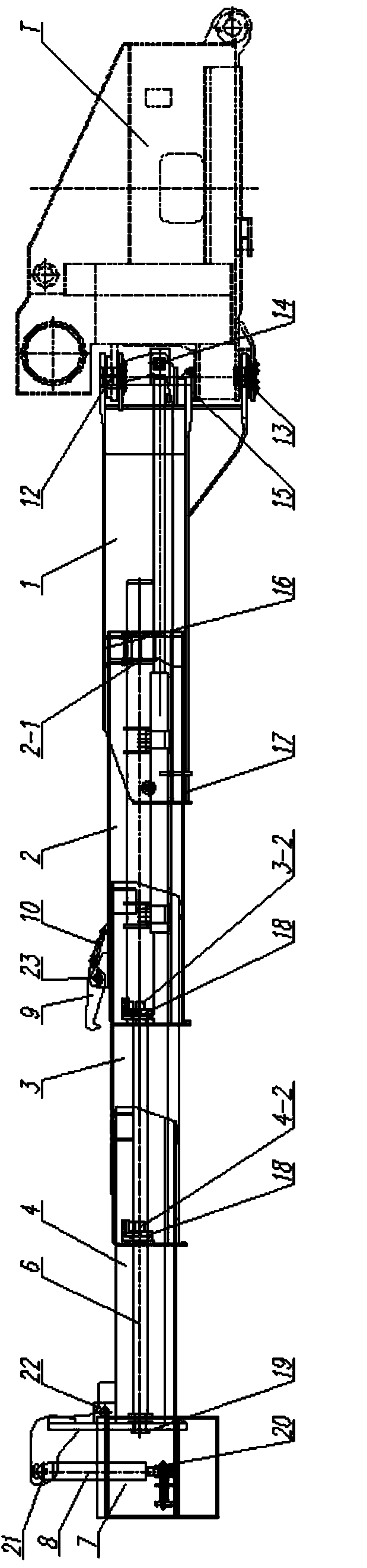
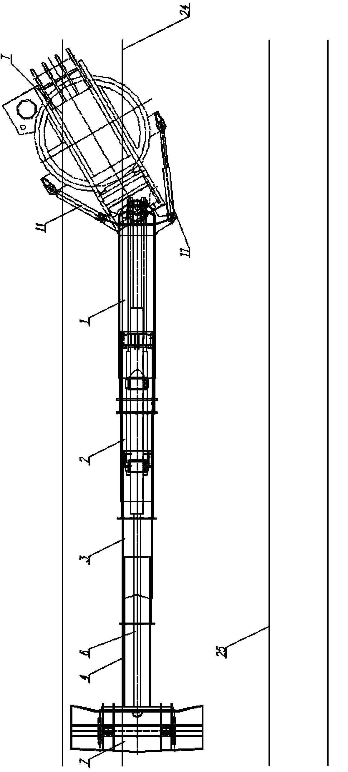
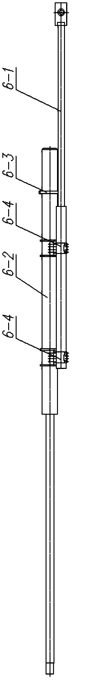
[0020] The swingable telescopic counterweight structure of the present invention includes a turntable, a telescopic arm, a counterweight body, an oil cylinder system, and a control system. The telescopic arm is composed of a basic arm, a two-section arm, a three-section arm, and a four-section arm. The joint arm 2, the three-joint arm 3 and the four-joint arm 4 are sequentially connected from outside to inside by sliding sets of sliders; the oil cylinder system is composed of a telescopic oil cylinder, a swing oil cylinder, a hanging oil cylinder and a lug oil cylinder, and the telescopic oil cylinder 6 is composed of the lower Two small oil cylinders 6-1 and an upper large oil cylinder 6-2 are composed, the lower two small oil cylinders 6-1 and the upper large oil cylinder 6-2 are connected by two flanges 6-4, and the telescopic oil cylinder 6 is connected by a flange plate 6 ...


PUM


Abstract

The invention relates to a swingable telescopic balance weight structure for a railway crane, belonging to the field of cranes. The swingable telescopic balance weight structure comprises a rotary table, a telescopic boom, a balance weight body, an oil cylinder system and a control system, wherein the telescopic boom comprises a base boom, a second-section boom, a third-section boom and a fourth-section boom which are sequentially connected from outside to inside by sliding blocks in a sleeving and supporting manner; the oil cylinder system comprises a telescopic oil cylinder, a swinging oil cylinder, a suspending oil cylinder and a suspension loop oil cylinder; the telescopic cylinder is composed of two small oil cylinders at the lower part and a large oil cylinder at the upper layer and is integrally arranged in the second-section boom. The swingable telescopic balance weight structure is simple in structure; by means of a connecting relationship between the oil cylinders at the upper part and the lower part and the four sections of boom, supporting guide of the sliding blocks among the four sections of the boom, and a combined action of suspension loops and baffle plates, the difficulty of the four sections of boom of the two stages of telescopic cylinder is solved, so that the four sections of balance weight boom can freely complete a sequential telescopic action; meanwhile, when the crane rotates for +/- 30 degrees for operation, the balance weight boom can rotate for 30 degrees towards a reverse direction relative to the rotary table, so that the balance weight does not interfere with the running of a train in an adjacent line along a track.

Description

technical field [0001] The invention relates to a swingable telescopic counterweight structure for railway cranes, belongs to the field of cranes, and particularly relates to railway cranes. Background technique [0002] Overturning and derailing accidents of railway rolling stock mostly occur on the track on which it is running or on the single-track railway near it, and the accident vehicle and the rescue crane are on the same track; on the double-track railway, the transportation of one line is interrupted due to an accident, All efforts must be made to ensure the smooth flow of the adjacent lines, and the rescue crane should strive to complete the rescue operation on a line that has been interrupted without affecting the normal operation of the adjacent line. Therefore, it has a large lifting capacity within the range of ±30° along the track, which is of great significance to railway rescue operations. [0003] During the operation of the railway crane, in order to make...

Claims


Application Information

Patent Timeline
Patent Type & Authority Applications(China)
IPC IPC(8): B66C23/72
Inventor 刘振营杜斌武赵世琏王炜杨威张敏何毅
Owner WUHAN BRIDGE INDUSTRIAL EQUIPMENT COMPANY LTD
Why Eureka
Try Eureka