
Method and apparatus for gas cleaning

A gas cleaning and equipment technology, applied in mechanical equipment, chemical instruments and methods, solid separation, etc., can solve problems such as difficulty in cleaning electrostatic dust filters, and achieve the effects of low power consumption, high collection efficiency, and high charge density

Inactive Publication Date: 2016-04-06
阿里·莱廷伦 +2
View PDF4 Cites 0 Cited by
  • Summary
  • Abstract
  • Description
  • Claims
  • Application Information

AI Technical Summary

Problems solved by technology

However, in that case the particles would deposit on all surfaces near the corona electrodes and this would make cleaning of the electrostatic precipitator more difficult

Method used


Image

  • Method and apparatus for gas cleaning
  • Method and apparatus for gas cleaning
  • Method and apparatus for gas cleaning

Examples


Embodiment Construction

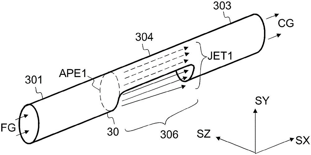
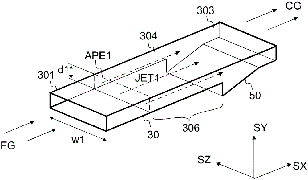
[0049] Referring to FIG. 1 , a gas cleaning apparatus 500 may include a particle charging unit 150 , a flow guiding structure 30 , and a particle collector 10 .

[0050] The particulate-laden gas FG may be introduced into the gas cleaning device 500 via an intake conduit 301 .

[0051] The particle charging unit 150 is configured to form charged particles P1 by charging the neutral particles P0 of the particle-laden airflow FG. The particulate-laden gas FG may eg be flue gas from a combustion process.

[0052] The particles P0 may eg be solid or liquid particles. The diameter of the particle P0 may for example be in the range of 5 nm to 500 nm.

[0053] The charging unit 150 may include an ion source 100 and an intake duct 301 . The ion source 100 is arranged to provide a flow of ionized gas IG. The ionized gas IG includes ions J1, such as Figure 1a shown by the black dots.

[0054] Ionized gas IG may be introduced into intake conduit 301 via nozzle 130 . The substantiall...


PUM


Abstract

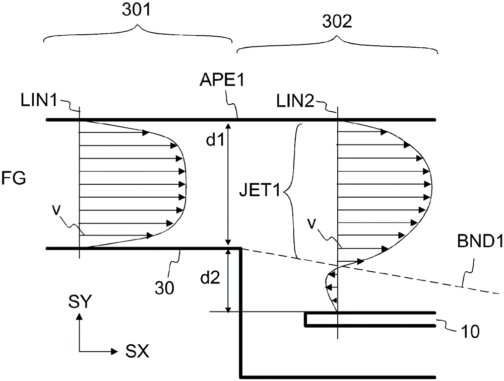
A method for separating particles (P0, P1) from a particle-laden gas (FG), comprising: - forming charged particles (P1) by charging the particles (P0) of the particle-laden gas (FG), - A guide structure (30) guides said particle-laden gas (FG) to provide a gas jet (JET1), - and collects particles (P1) from said gas jet (JET1) to a collector electrode (10) by means of an electric field (E1), wherein The effective collection zone (EFFZ) of the collector (10) is positioned such that the gas velocity gradient (Δv / Δy) at each point of the effective collection zone (EFFZ) is smaller than the maximum gas velocity in the gas jet (JET1) Velocity (VMAX) divided by 10% of the jet's height dimension (d1').

Description

technical field [0001] The present invention relates to the separation of particles from gases. Background technique [0002] For example, when burning wood, wood pellets, peat or municipal waste, aerosol particles may be formed during the combustion process. Aerosol particles can also be formed in industrial processes such as hot-dip galvanizing, welding or glass melting. The aerosol particles are generally harmful to the environment and health. Specifically, so-called nanoparticles can cause health problems when inhaled, as they can penetrate the human lungs. Toxic heavy metals that evaporate during industrial processes may also become concentrated and become enriched in nanoparticles. The term nanoparticle herein refers to particles having a diameter less than or equal to 500 nm. [0003] It is known that aerosol particles can be separated from the flue gas by using filtration, or by using electrostatic precipitators. Electrostatic precipitators are generally charact...

Claims


Application Information

Patent Timeline
Patent Type & Authority Patents(China)
IPC IPC(8): B03C3/45B03C3/12B03C3/36B03C3/14F02C7/052
CPCB03C3/12B03C3/14B03C3/366B03C3/47B03C3/38B03C3/08B03C3/41B03C3/45
Inventor 阿里·莱廷伦考科·詹卡乔马·凯斯金伦
Owner 阿里·莱廷伦
Learn More