
A Calculation Method for Pile Raft Foundation Structure

A calculation method and technology of piled raft foundation, applied in the direction of foundation structure engineering, construction, etc., can solve the problems of large actual internal force of raft slab, inconsistent calculation results, inability to distribute longitudinal and lateral loads of slab strips, etc., to achieve convenient calculation and calculation work Small amount of effect

Active Publication Date: 2016-05-04
SHANGHAI WATER ENG DESIGN & RES INST
View PDF2 Cites 0 Cited by
  • Summary
  • Abstract
  • Description
  • Claims
  • Application Information

AI Technical Summary

Problems solved by technology

[0010] ①The rigid slab method is based on the fact that the pile top loads are equal, but the pile top reaction forces are not equal, but the angle piles and side piles are large, the internal piles are small, and the difference in the pile top reaction force will cause the actual internal force of the raft to be larger than the calculated result. Therefore, the calculation result of raft internal force by this method is unsafe
[0011] ②The rigid plate method ignores the deformation coordination and internal force between the plates, and its calculation results are inconsistent with the actual situation
[0012] ③The rigid plate method cannot distribute longitudinal and transverse loads to the strips, and the loads at the intersections of the longitudinal and horizontal strips are directly applied to the longitudinal and horizontal strips in the calculation
With this method, usually only finite element analysis and calculation can be used, but finite element calculation has a large amount of calculation work, and the foundation parameters are inconvenient to determine, so it is difficult to be directly used in engineering design. can be used as a reference calculation
Secondly, the influence of the hydraulic superstructure on the foundation is small, so the joint action analysis is rarely done in the hydraulic calculation
[0019] In summary, the above-mentioned calculation methods currently used are difficult to truly reflect the actual stress of the piled raft structure. To solve these problems, it is necessary to innovate in the calculation model, so as to provide convenient calculation and better calculation results for engineering design. Calculation model in line with the actual force situation

Method used


Image

  • A Calculation Method for Pile Raft Foundation Structure
  • A Calculation Method for Pile Raft Foundation Structure
  • A Calculation Method for Pile Raft Foundation Structure

Examples


Embodiment Construction

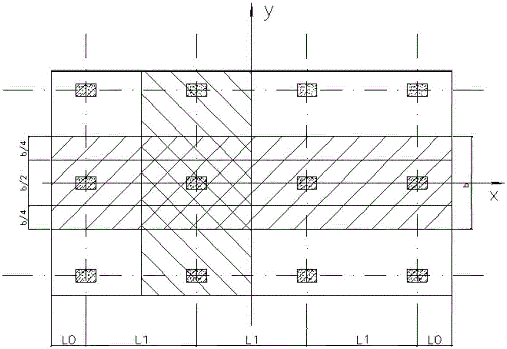
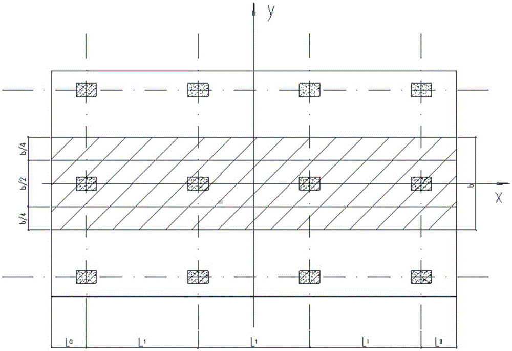
[0057] In order to make the technical means, creative features, goals and effects achieved by the present invention easy to understand, the present invention will be further described below in conjunction with specific illustrations.

[0058] A calculation method for a piled raft foundation disclosed by the present invention is described from three aspects as follows.

[0059] 1) Basic principles

[0060] Pile-raft foundations are widely used in hydraulic foundation engineering. According to a large number of test results and monitoring data, the stress and deformation characteristics of pile-raft foundations are that when the pile-raft bears a load not greater than the design load, its static load test The p ~ s curve is basically linear.

[0061] The greater the displacement of a certain point in the foundation, the greater the compression of the point, and the greater the elastic resistance strength of the corresponding soil or pile to the foundation. This relationship is ...


PUM


Abstract

The invention discloses a calculation method for a piled raft infrastructure. The calculation method comprises the following steps: firstly, stiffness calculation: a, under the condition that the bearing capacity of earth among piles is not considered, a pile foundation can be simulated as a spring, and the spring stiffness kpi of the foundation pile can be expressed by the ratio of the pile top load Qdi to the pile top settlement si; b, the combined action of the piles and the earth is considered, the load borne by the earth among the piles is about 15 percent of the total load; secondly, infrastructure calculation: for foundations simulated by adopting spring supporting seats, each spring supporting seat is used as a unit, the units are integrated according to certain conditions, and a total stiffness matrix is formed by assembling unit stiffness matrixes. The spring supporting seats are adopted for simulating the foundations of the pile foundations and common settlement in the engineering is used for analyzing, so that the defect that part of parameters is difficult to determine by an elastic method is overcome; by adopting spring models which are close to actual conditions of the interaction of the pile earth and the structure, the calculating workload is small, the calculation is convenient, and the calculation result accords with the requirement of engineering design.

Description

technical field [0001] The invention relates to hydraulic structure calculation technology, in particular to a calculation method for piled raft foundation structure. Background technique [0002] The piled raft foundation refers to the use of pile foundations under the raft foundation, referred to as the piled raft foundation. Pile-raft foundations are widely used in water conservancy projects. On natural foundations, especially soft soil foundations, hydraulic structures are often difficult to meet the requirements of stability and settlement. Pile foundations are an ideal foundation form, and hydraulic structures are raft-shaped foundations. When the piles are used under the raft foundation, the piled raft foundation is formed. For example, most of the buildings such as pump houses, lock chambers, and retaining walls on soft soil foundations are raft foundations. When pile foundations are used, pile raft foundations are formed. [0003] Due to its complexity, the founda...

Claims


Application Information

Patent Timeline
Patent Type & Authority Patents(China)
IPC IPC(8): E02D27/01
Inventor 唐金忠潘世虎
Owner SHANGHAI WATER ENG DESIGN & RES INST
Learn More