
Kalman filter channel-based pulse stacking correction method

A Kalman filter and pulse stacking technology, applied in the fields of digital signal processing, nuclear electronics technology, and nuclear radiation detection, can solve problems such as energy spectrum distortion and computational complexity

Active Publication Date: 2018-01-16
CHENGDU UNIVERSITY OF TECHNOLOGY
View PDF5 Cites 12 Cited by
  • Summary
  • Abstract
  • Description
  • Claims
  • Application Information

AI Technical Summary

Problems solved by technology

[0006] The purpose of the present invention is to provide a pulse pile-up correction method based on the Kalman filter channel, which mainly solves the problems of complex calculation and energy spectrum distortion in the prior art.

Method used


Image

  • Kalman filter channel-based pulse stacking correction method
  • Kalman filter channel-based pulse stacking correction method
  • Kalman filter channel-based pulse stacking correction method

Examples


Embodiment 1

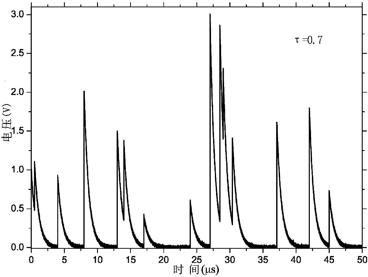
[0091] Such as figure 2 As shown, the present embodiment only produces 15 nuclear pulse waveforms S with the pulse shaper 1 It is described as the basic data, and other situations are implemented in the same way, and will not be described in detail below. Since the nuclear pulse signal is random, it is only necessary to set the amplitude of the initial point to be 0 when the nuclear pulse signal is initialized.

[0092] Suppressed nuclear pulse waveform S 1 weak signal, nuclear pulse waveform S 1 After identifying and extracting, Figure 3 to Figure 6 In order to obtain the waveform S after filtering by the Kalman filter 2 the result of. It can be seen from the comparison that it can be well applied to the case of 4 nuclear pulse accumulations.

[0093] Since the noise also has a great influence on the separation process of the accumulation pulse, by adding the accumulation events of Gaussian white noise with different variances, and using the variance δ ω Come simulat...

Embodiment 2

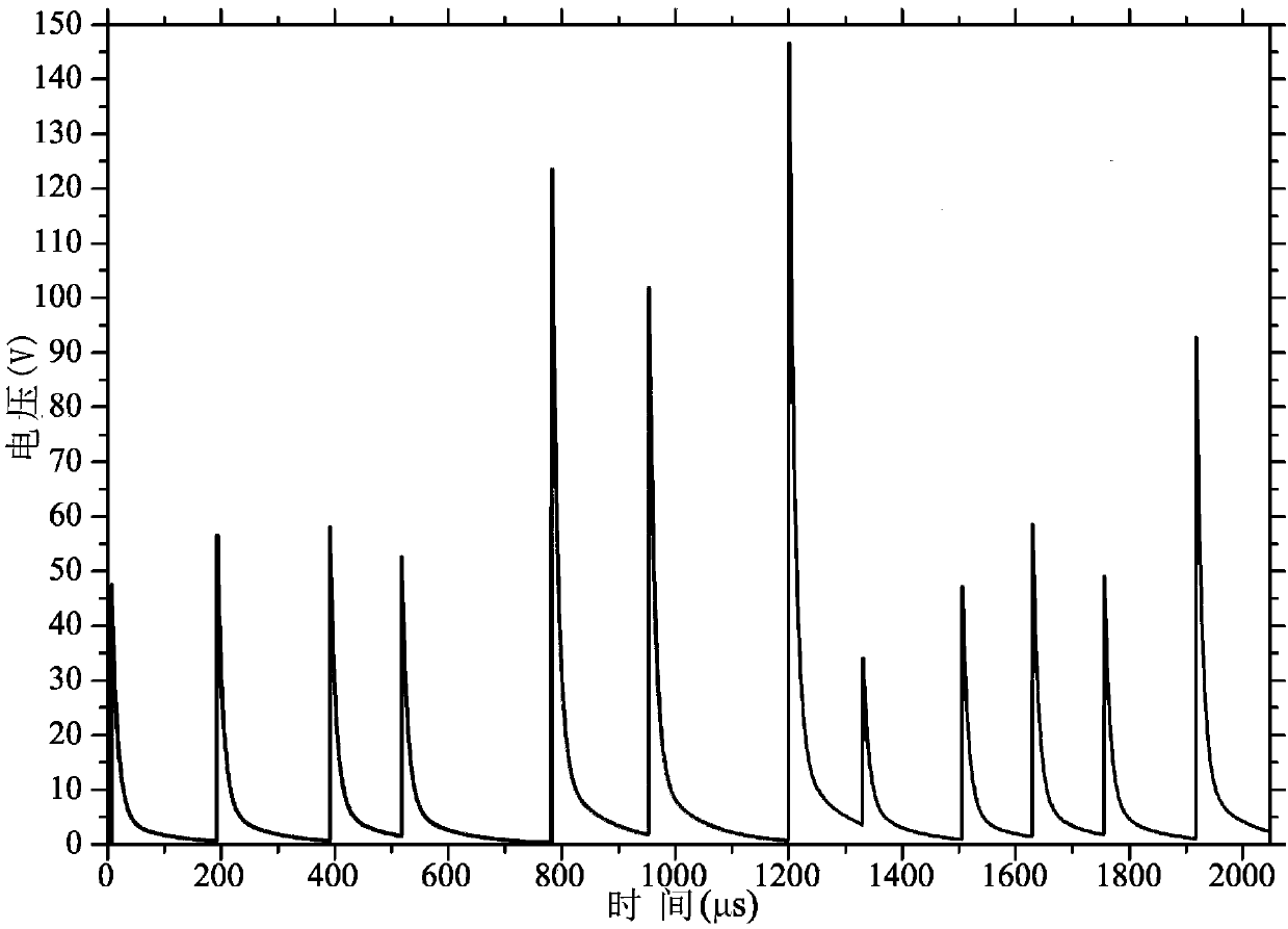
[0097] The X-ray from the spherical X-ray tube is detected by the X-ray detector, and the waveform detected by the detection card is as follows: Figure 11 As shown, after the waveform is corrected by the pulse pile-up of the present invention, the separation state obtained is as follows Figure 12 to Figure 15 It can be seen from the comparison that the present invention has the ability of X-ray pulse stacking and separation.

[0098] To sum up, the present invention skillfully uses the Kalman filter to propose a method to solve the pulse accumulation event, which not only can effectively separate the pulse accumulation, but also has good anti-noise ability and reduces the distortion rate of the X-ray energy spectrum. After repeated tests by the applicant, the present invention has the advantages of high computing speed, strong anti-noise ability, low energy spectrum distortion, and high pulse separation precision. It can be said that compared with the prior art, it has outst...


PUM


Abstract

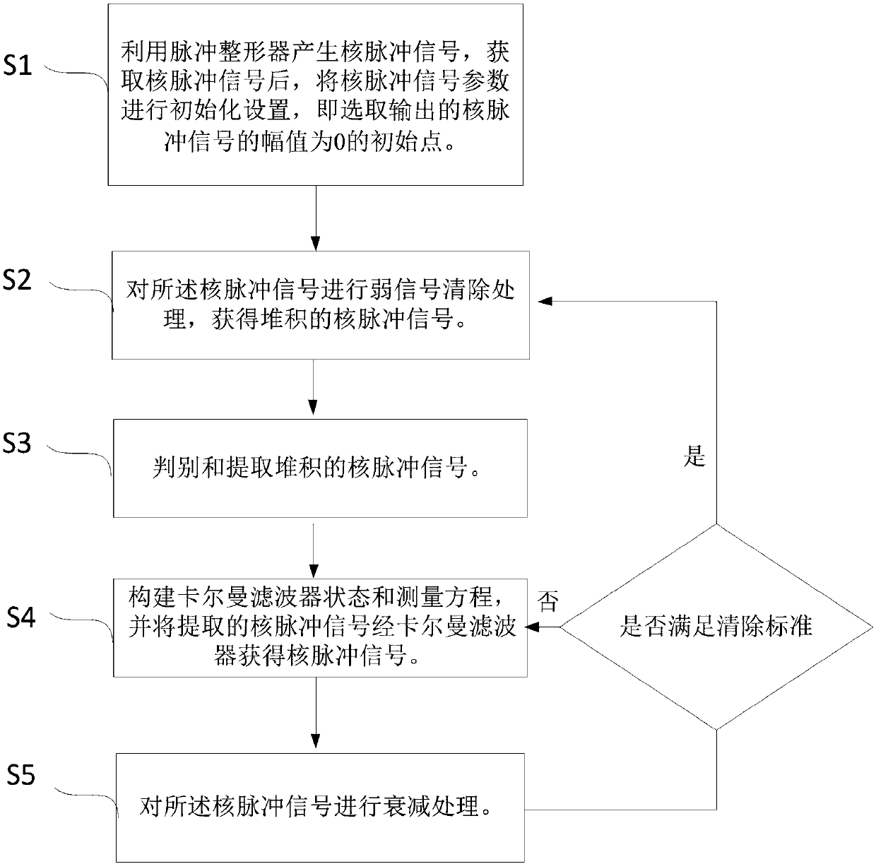
The present invention discloses a Kalman filter channel-based pulse stacking correction method which mainly solves the problems in the prior art that the calculation is complex, an energy spectrum distorts, etc. The method comprises the following steps of utilizing a pulse shaper to generate a nuclear pulse signal Sn, obtaining the nuclear pulse signal Sn and then initializing the parameters of the nuclear pulse signal Sn, namely, selecting an initial point where the amplitude X0 of the outputted nuclear pulse signal Sn is 0; carrying out the weak signal removing processing on the nuclear pulse signal Sn, and obtaining the stacked nuclear pulse signals S1n; determining and extracting the stacked nuclear pulse signals S1n; constructing a Kalman filter state and measurement equation, and using a Kalman filter to process the extracted nuclear pulse signals S1n to obtain the nuclear pulse signals S2n; attenuating the nuclear pulse signals S2n, and determining whether to satisfy a removingstandard. By the above scheme, the Kalman filter channel-based pulse stacking correction method of the present invention achieves the purpose of separating the stacked pulse events, and has the very high practical value and popularization value in the nuclear radiation detection, the nuclear electronics technology and the digital signal processing fields.

Description

technical field [0001] The invention relates to the fields of nuclear radiation detection, nuclear electronics technology, digital signal processing and the like, especially a pulse accumulation correction method based on a channel of a Kalman filter. Background technique [0002] Pile-up events are a critical problem for X(γ) counting and spectroscopy systems, especially in the presence of high-density sources of parametric X-ray and positron emission tomography (PET). As one of two sources of uncertainty, pile-up is caused by the intrinsic factor that particles arrive within microsecond-scale time intervals such that detectors cannot eliminate subsequent events of accurate response from previous radiation events, resulting in overlap between individual pulses. The site produces a signal. Pulse pile-up results in reduced throughput, increased dead time, and reduced energy resolution, resulting in reduced performance of the radiation detection system. [0003] With the con...

Claims


Application Information

Patent Timeline
IPC IPC(8): G01T7/00G01T1/36
Inventor 刘明哲杨凤何明富刘艳华蒋鑫柳炳琦
Owner CHENGDU UNIVERSITY OF TECHNOLOGY
Learn More