A robot hand-eye calibration method based on two degrees of freedom 3D vision sensor

A visual sensor and calibration method technology, which is applied to instruments, measuring devices, optical devices, etc., can solve problems such as limitations of navigation capabilities, and achieve the effects of high measurement accuracy, high calculation accuracy and simple method.

Active Publication Date: 2016-10-26
HEFEI INSTITUTES OF PHYSICAL SCIENCE - CHINESE ACAD OF SCI +1
View PDF7 Cites 0 Cited by
  • Summary
  • Abstract
  • Description
  • Claims
  • Application Information

AI Technical Summary

Problems solved by technology

However, there is a problem in the prior art that the navigation capability is limited by the field of view of the 3D vision sensor. In order to expand the field of view, it is necessary to increase the degree of freedom of the sensor in the horizontal and vertical directions, so as to drive the 3D vision sensor to perform larger Scene information collection from field of view angles

Method used


Image

  • A robot hand-eye calibration method based on two degrees of freedom 3D vision sensor
  • A robot hand-eye calibration method based on two degrees of freedom 3D vision sensor
  • A robot hand-eye calibration method based on two degrees of freedom 3D vision sensor

Examples


Embodiment Construction

[0015] Further describe the present invention below in conjunction with embodiment and accompanying drawing thereof:

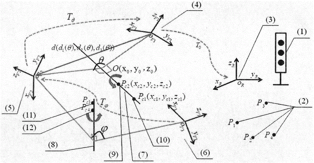
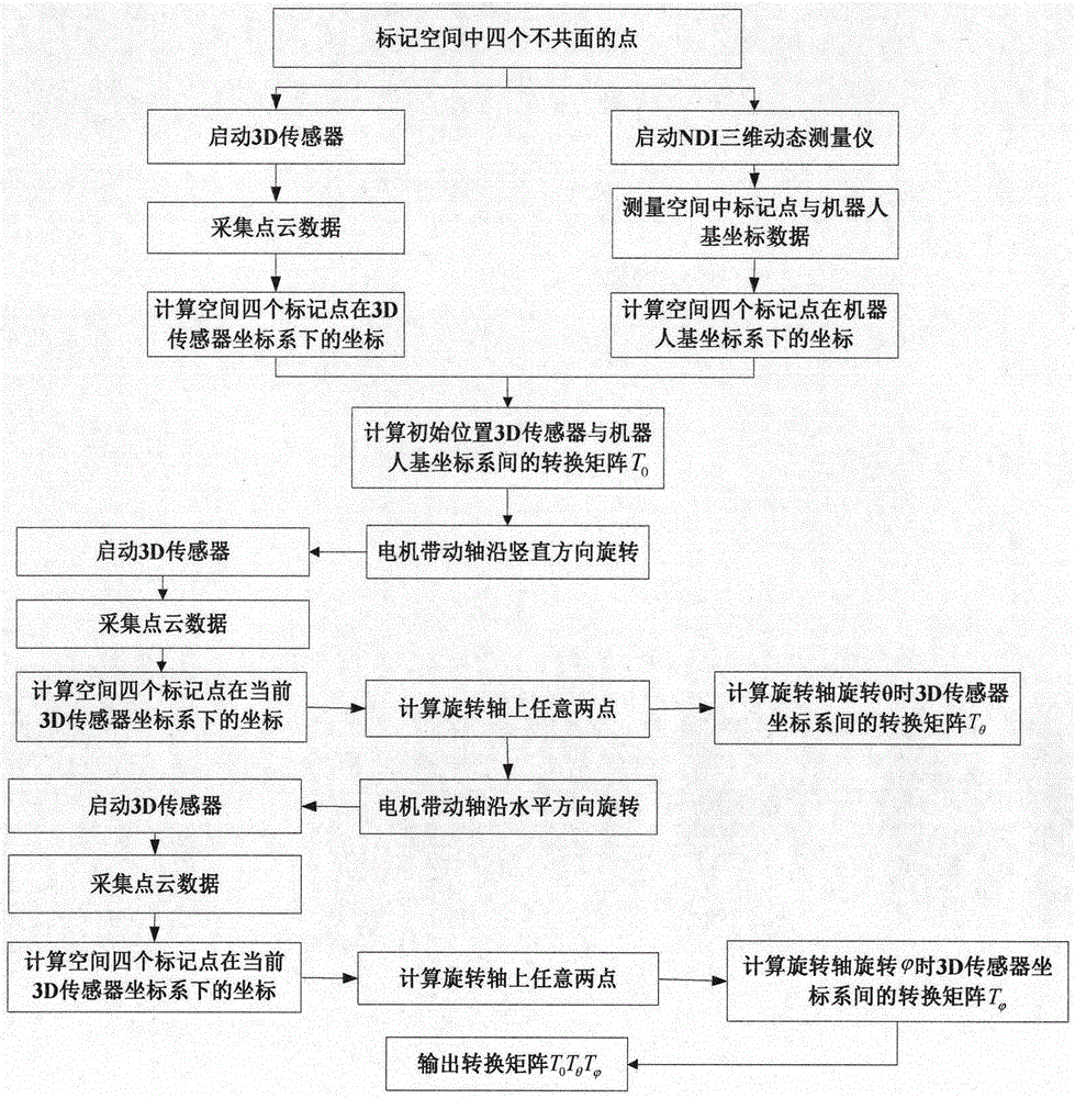
[0016] like Figure 1 to Figure 4 As shown in the present invention, a robot hand-eye calibration method based on a two-degree-of-freedom 3D vision sensor, the rotation angles of the robot head in the vertical direction and the horizontal direction relative to the initial position are respectively θ, , the calibration process is mainly divided into the following steps:

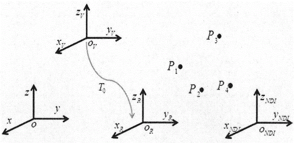
[0017] The first step is the coordinate transformation matrix T between the initial position visual coordinate system and the robot base coordinate system 0 calculation;

[0018] Pick four points P that are not coplanar in space 1 , P 2 , P 3 , P 4 , obtain the three-dimensional coordinates of four points in the visual coordinate system through the visual sensor, which are respectively recorded as:

[0019] P V1 (x v1 ,y v1 ,z v1 ), P V2 (x v2 ,y v2 ,z v2 ), P V3 (x v3 ,y v3...


PUM


Abstract

The invention provides a robot hand-eye calibration method based on a two-degree-of-freedom 3D visual sensor, comprising the following steps: the first step, the coordinate transformation matrix T between the initial position visual coordinate system and the robot base coordinate system 0 The calculation; the second step, the visual sensor is rotated from the initial position in the vertical and horizontal directions by angle θ and After that, the transformation relationship matrix T between the coordinate systems θ and In the third step, the hand-eye transformation relationship matrix can be obtained by multiplying the transformation matrices; the present invention has the advantages of simple method, high measurement accuracy, easy promotion, etc., and can effectively meet the needs of robot hand-eye calibration.

Description

technical field [0001] The invention relates to the technical field of industrial robot vision calibration, in particular to a robot hand-eye calibration method based on a two-degree-of-freedom 3D vision sensor. Background technique [0002] With the application and development of 3D vision sensor vision technology, more and more robots use 3D vision sensor as an important tool for their autonomous navigation. However, there is a problem in the prior art that the navigation ability is limited by the field of view of the 3D vision sensor. In order to expand the field of view, it is necessary to increase the degree of freedom of the sensor in the horizontal and vertical directions, so as to drive the 3D vision sensor to perform larger Scene information collection from field of view angles. Contents of the invention [0003] In view of the deficiencies in the prior art, the technical problem to be solved by the present invention is to provide a robot hand-eye calibration met...

Claims


Application Information

Patent Timeline
Patent Type & Authority Patents(China)
IPC IPC(8): G01B11/00
Inventor 谭治英骆敏舟李涛方世辉罗艳赵娜娜郑俊君孙晓瑜黄海卫
Owner HEFEI INSTITUTES OF PHYSICAL SCIENCE - CHINESE ACAD OF SCI
Why Eureka
Try Eureka