
Fatigue test device for torque arm assembly

A technology of fatigue test and torsion arm, which is applied in the direction of measuring devices, testing of mechanical components, testing of machine/structural components, etc., can solve the problems of simplification of large projects and inability to truly simulate the load transfer relationship, etc., and achieve accurate and credible results Effect

Active Publication Date: 2014-12-24
CHINA HELICOPTER RES & DEV INST
View PDF7 Cites 10 Cited by
  • Summary
  • Abstract
  • Description
  • Claims
  • Application Information

AI Technical Summary

Benefits of technology

This new design allows for better simulation on how long it takes during use without causing damage or affects its performance. It uses both an upper and lower set of force-generating devices that applies forces onto specific parts of the system called the twist arm assemblies (TWA). These tests demonstrate that this configuration accurately replicates what happens when there're no external influences like vibrations or impacts from outside. Overall, these technical improvements help improve safety measures by reducing errors caused by factors such as stress concentration and wear debris accumulation over time.

Problems solved by technology

The technical problem addressed in this patented text relates to simulation testing on structures such as Helmets that have twist-arm systems attached at both ends (the movement rings) to transmit force from an upstream direction towards down stream directions during flight operations. This requires accurate simulations overall, but current methods may result in errors due to factors like stress concentration caused by repeated impacts between different parts of the system's components.

Method used


Image

  • Fatigue test device for torque arm assembly
  • Fatigue test device for torque arm assembly
  • Fatigue test device for torque arm assembly

Examples


Embodiment Construction

[0017] The present invention will be described in further detail below.

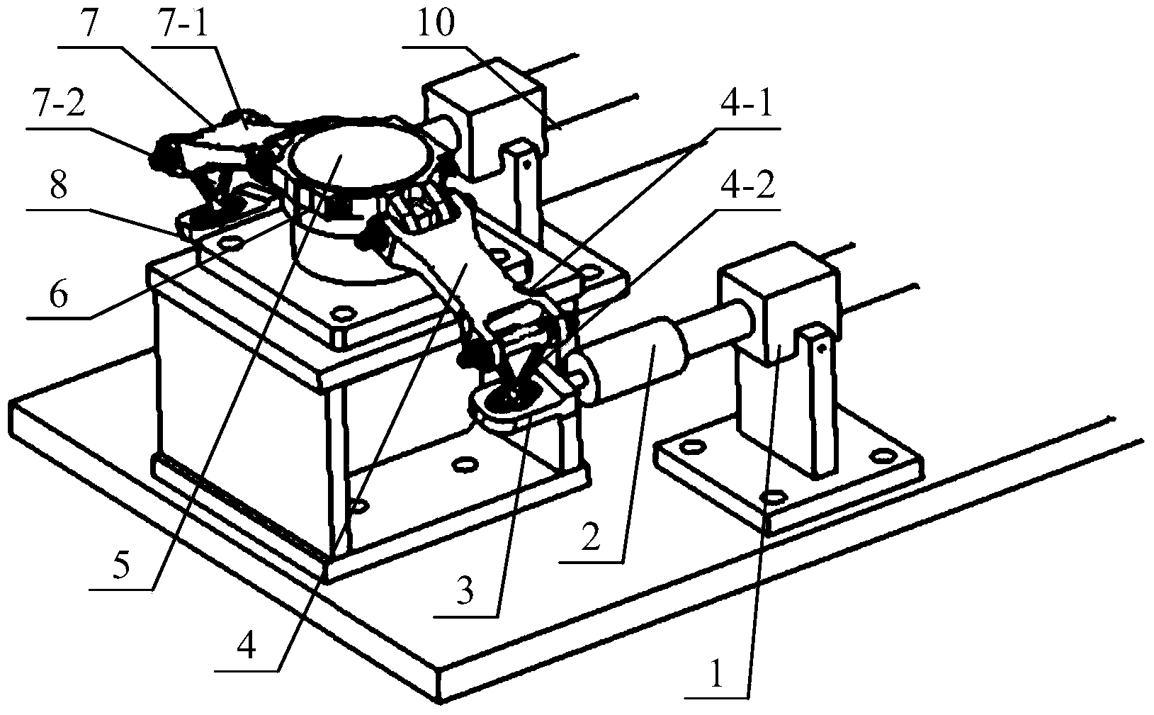
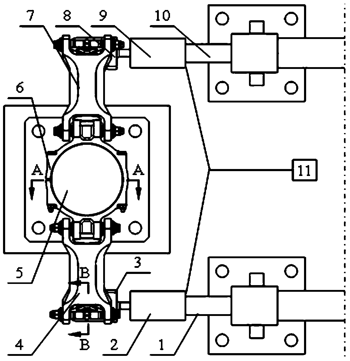
[0018] Such as figure 1 , figure 2 , image 3 , Figure 4 As shown, the present invention is a torsion arm assembly fatigue test device, comprising:

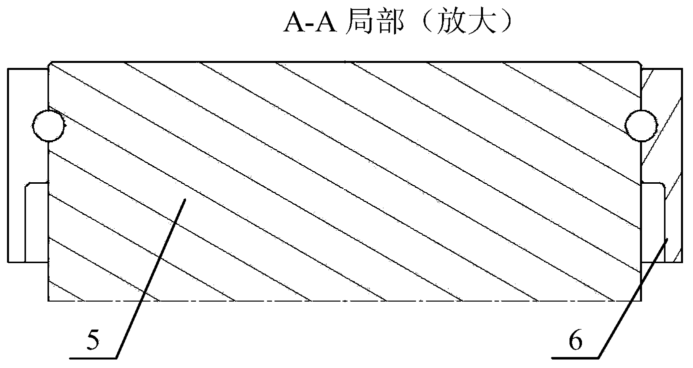
[0019] Spindle dummy 5, No. 1 actuator 1, No. 1 load cell 2, No. 1 loading joint 3, No. 2 actuator 10, No. 2 load cell 9, No. 2 loading joint 8, coordinated loading control system 11 , there are two opposite semicircular holes on the shaft body of the main shaft dummy part 5, the outer diameter of the main shaft dummy part 5 is adapted to the inner diameter of the snap ring 6, and is aligned with the two opposite semicircular holes on the snap ring 6, and the connecting bolt passes through the The semicircular hole on the main shaft dummy and the snap ring connects the main shaft dummy and the snap ring, and the snap ring is fixed on the main shaft dummy by tightening the connecting bolts. The No. 1 actuator 1 is connected with the No. 1 load cell 2 ...


PUM


Abstract

The invention discloses a fatigue test device for a torque arm assembly and belongs to the fatigue test technology for torque arm assemblies. The fatigue test device for the torque arm assembly is characterized in that two opposite semicircular holes are formed in one end of a shaft body of an artificial main shaft, the outer diameter of the shaft body of the artificial main shaft is matched with the inner diameter of a clamping ring, the two semicircular holes in the shaft body and two opposite semicircular holes in the clamping ring are aligned, and the other end of the artificial main shaft is fixed to a test stand rack; a first actuator is connected with a first force transducer and is connected with a first torque arm through a first loading connector, a second actuator is connected with a second force transducer and is connected with a second torque arm through a second loading connector, the first actuator and the second actuator are symmetrical about the artificial main shaft, a pair of loads which are opposite in direction are exerted on the first loading connector and the second loading connector respectively in the tangential directions of the torque arms, and the fixed end of the first actuator and the fixed end of the second actuator are fixed to the test stand rack. According to the fatigue test device for the torque arm assembly, the loading structure and the load characteristics can be simulated more truly, and results are more accurate and more credible. When the fatigue test device is used for testing, the overall testing error can be controlled below 3%.

Description


Claims


Application Information

Patent Timeline
Owner CHINA HELICOPTER RES & DEV INST
Learn More