
Wild game attraction device and method

Inactive Publication Date: 2006-05-16
HUNTWISE
View PDF18 Cites 43 Cited by
  • Summary
  • Abstract
  • Description
  • Claims
  • Application Information

AI Technical Summary

Benefits of technology

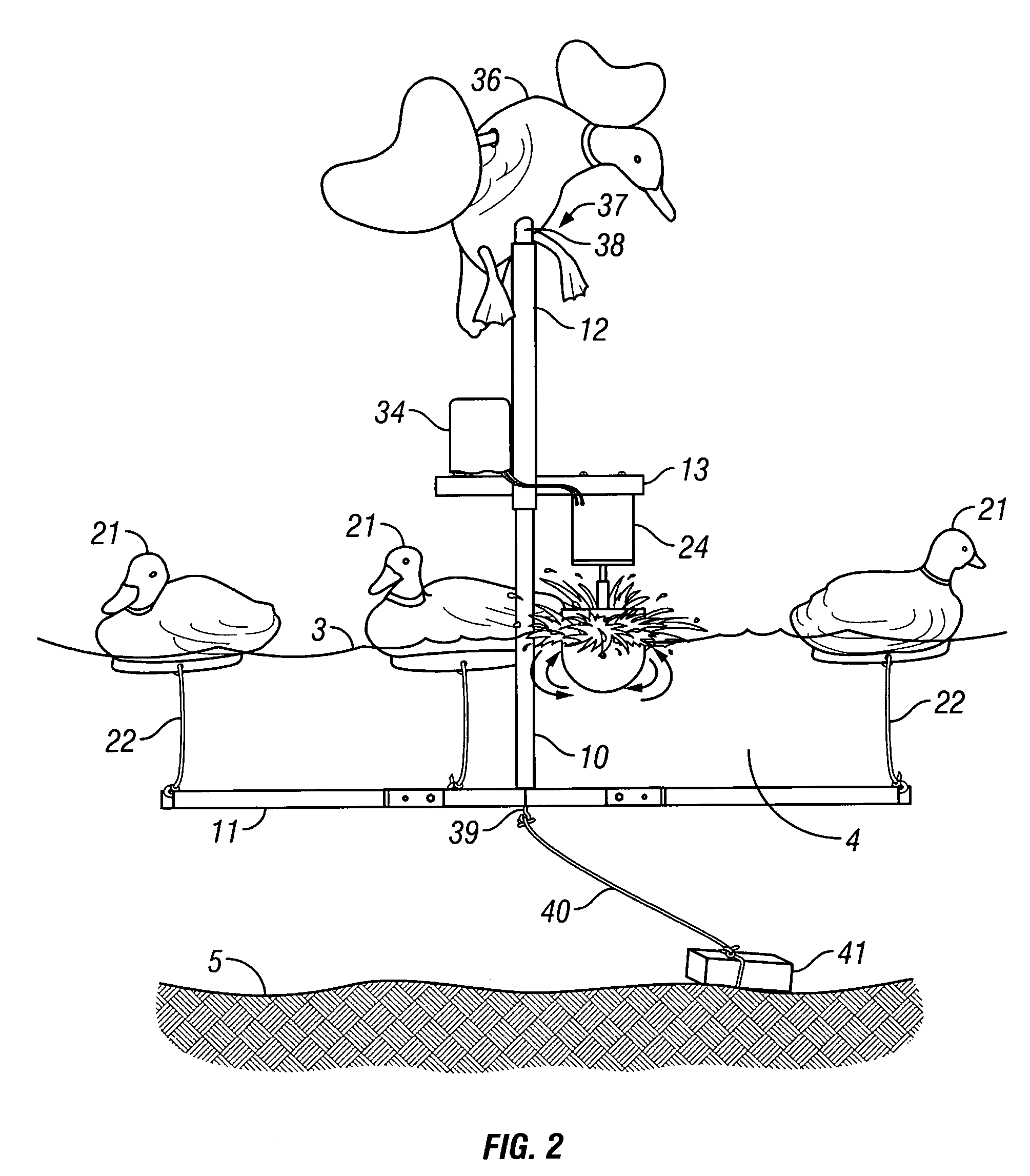
[0020]Another object of the present invention is to provide a device for agitating the surface of the water body on which the device is deployed, in a manner that simulates the appearance and sound of swimming, feeding, bathing, and commingling live waterfowl.
[0024]Another object of the present invention is to provide a device for agitating the surface of the water body on which the device is deployed, wherein the legs of the frame may be folded towards the frame for ease of transport.
[0025]Another object of the present invention is to provide a device for agitating the surface of the water body on which the device is deployed, wherein the device is lightweight and easily deployed in the field.
[0026]Another object of the present invention is to provide a device for agitating the surface of the water body on which the device is deployed, wherein the device is durable and holds up well under the rigors presented by ordinary hunting conditions.
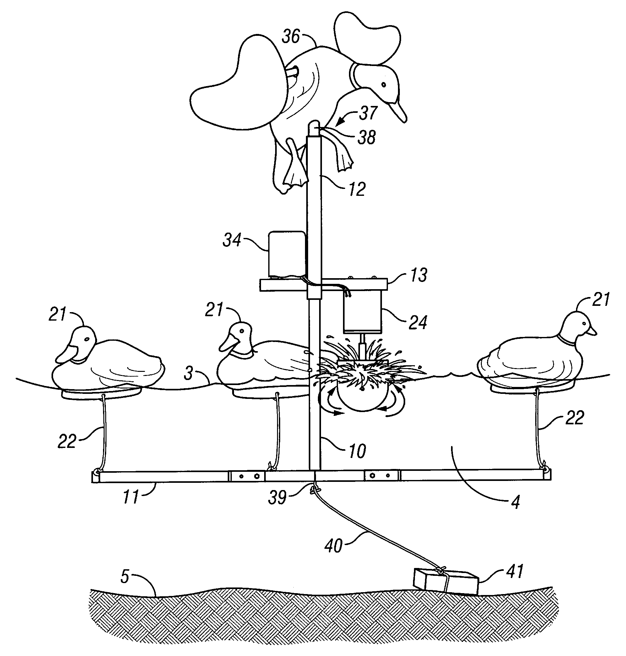
[0030]The frame may be floated in a body of water by using a floating means, which may include a plurality of floating decoys. The floating means are attached to the distal ends of the legs, which must first be locked in the horizontal position using the aforementioned locking means. In this manner, the leg members and a portion of the vertical member are suspended beneath the water surface and are prevented from sinking by virtue of the floating means.
[0035]Another embodiment of the invention involves the addition of a modulator or a multi-cycle remote control to the motor whereby the user can modify the duration and frequency of operation in order to provide a more realistic simulation of waterfowl activity.

Problems solved by technology

Most waterfowl spend significant amounts of time swimming, feeding, resting, sleeping, bathing, and co-mingling with like species, all of which occur on various bodies of water and cause considerable disturbance of the water surface.
Past attempts to attract waterfowl to a particular hunting area have proven ineffective due to the exceptionally sharp hearing and eyesight of game birds.
The very first decoys appealed only to the visual senses of the waterfowl, as they were merely “static” imitations of a live bird and did not provide any means by which the decoy could be moved or produce life-like sounds.
The disadvantage of each of the above systems is that none provide a means for moving the decoys, nor do any of them appeal to the waterfowl's auditory sense.
Although Becker accomplishes the movement of duck decoys from a remote hunting location, the device is heavy, difficult to assemble in the field, lacks realistic waterfowl movement, and does not create any splashing or noise comparable to live waterfowl movement.
Like Becker, the McCrory device is difficult to transport and / or assemble and lacks realistic waterfowl movement.
More importantly, McCrory, like Becker, does not create splashing or rippling on the water surface in amounts sufficient to convince live waterfowl that the hunting area is safe for landing or occupation.
In particular, the Yerger device only allows the user to adjust the amount and degree of ripples by changing the length or position of the stake or anchor cord.
Additionally, because the motor remains completely submerged, the device will not likely create the proper amount and type of noise needed to attract waterfowl.
Furthermore, the user of the Yerger ruffling system will likely find it difficult to achieve the desired amount of movement of the surrounding decoys, which are deployed independently of the device.
Finally, the Yerger device is difficult to deploy and retrieve due to its underwater orientation and because the length of the stake or anchor cord must be reconfigured each time the device is relocated to another section of the pond.
The most important drawback of Yerger is that it uses an underwater motor, which is commonly known by those of skill in the art to be susceptible of performance problems and require continual maintenance and adjustment.
Additionally, the device would be difficult to locate if it were to break down while underwater.
The obvious disadvantage of using the Capps device is that it is not portable.
In fact, once the Capps decoy “racetrack” is installed in a given pond, it will unlikely ever be moved.
The device is not easily installed or repaired when the water is high, and therefore the user must install or repair the device when the water level in the pond is very low.
Additionally, the only noise associated with the device is that associated with the turning of the pulleys and the movement of the decoys through the water, neither of which simulates the sound of ducks feeding or commingling.
The principal disadvantage of Brock is that the device operates using an underwater motor.
Underwater motors such as those used in Yerger and Brock are expensive to purchase and require routine maintenance due to the corrosion caused by long periods of submersion.
Additionally, the Brock device is not capable of maintaining a continuous splashing and rippling action on the surface of the water, because once the Brock motor is activated, the frame is pushed away from the water surface and down towards the bottom of the water body.
Furthermore, the character and amount of ripples and splashing cannot be controlled using the Brock device because it is difficult to alter the distance between the underwater motor and the water surface once the decoy system is deployed.
As can be seen from the above discussion, the prior art has largely failed to capitalize on the visual and auditory stimuli of a flying waterfowl and has failed to develop a decoy system that is inexpensive, yet durable under ordinary hunting conditions.

Method used


Image

  • Wild game attraction device and method
  • Wild game attraction device and method
  • Wild game attraction device and method

Examples


Embodiment Construction

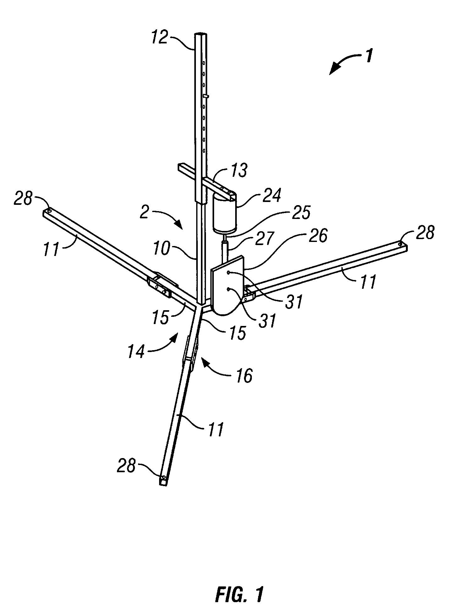
[0049]With reference to FIGS. 1–4c, a preferred embodiment of the wild game attraction device 1 will now be described. As shown in FIGS. 1 and 2, device 1 comprises a frame 2, which is disposed partially above and partially below water surface 3. Frame 2 is primarily comprised of vertical member 10, legs 11, telescoping member 12, and agitator assembly support 13. The various elements comprising frame 2 may be fashioned from any sufficiently durable material, including, but not limited to, metal, plastic, or wood.

[0050]Regardless of the material used to construct frame 2, the comprising members may have various cross sections, including, but not limited to cross sections that are cylindrical, square, rectangular, triangular or angled (such as a piece of angle iron).

[0051]Vertical member 10, which is oriented in a substantially vertical direction, may be perpendicularly attached to base structure 14, which is generally formed by welding or molding together the proximal ends of three ...


PUM


Abstract

A floating decoy system is provided for agitating the surface of a water body on which the device is deployed in a manner that is attractive to live game animals (e.g. live waterfowl). The system includes a frame, which is disposed partially above and partially below the surface of the water and suspended from a plurality of floating means. The device also includes an agitator assembly, which is slidably mounted to the frame above the surface of the water and produces ripples on the water surface and the sound of splashing water. The ripples and sound of splashing water are intended to simulate an active area where wild game are swimming, feeding, and interacting. Additionally, an airborne decoy may be mounted atop the frame to give the device added attractiveness to wild game. An alternative embodiment requires the removal of floating means and the anchoring of the frame to the bottom of the water body. The invention further includes a method for attracting live game animals to a target area by agitating the surface of a water body in a manner that simulates the appearance and sound of swimming, feeding, bathing, and commingling live game.

Description

CROSS-REFERENCE TO RELATED APPLICATION[0001]Not applicable.BACKGROUND OF THE INVENTION[0002]1. Field of the Invention[0003]This invention relates, generally, to wild game decoys, and in particular to motorized systems which simulate and attract wild game by agitating the water surface and by indirectly animating decoys in a decoy spread.[0004]2. Description of Related Art[0005]Outdoor enthusiasts and recreational hunters have long recognized that live game, and particularly live waterfowl, are attracted to areas that appear to be inhabited by similar animals. For this reason, hunters have used decoys to attract live game to within shooting distance of a hunter's rifle or shotgun. However, in order to attract live game animals to within the proper distance, the decoy must adequately reproduce the appearance, movement, and sound of the animal that they are designed to simulate.[0006]Most waterfowl spend significant amounts of time swimming, feeding, resting, sleeping, bathing, and co-...

Claims


Application Information

Patent Timeline
IPC IPC(8): A01M31/06
CPCA01M31/06A01M31/04
Inventor CROWE, CLAUDE M.
Owner HUNTWISE
Learn More