Laser antireflection film designing method for film layer with non-uniform refractive index

A non-uniformity and design method technology, applied in the direction of coating, etc., can solve problems that cannot be completely eliminated and affect spectral performance

Inactive Publication Date: 2014-12-24
THE 3RD ACAD 8358TH RES INST OF CASC
View PDF3 Cites 5 Cited by
  • Summary
  • Abstract
  • Description
  • Claims
  • Application Information

AI Technical Summary

Problems solved by technology

[0003] However, the non-uniformity of the refractive index of the film prepared based on the ion beam sputtering deposition method is relatively obvious, and the optical film grown under the non-equilibrium physical process generally has a certain degree of non-uniformity of the refractive index in the thickness growth direction. The size of non-uniformity is closely related to the deposition method, deposition process parameters, and surface properties of the substrate
Although the non-uniformity of the refractive index can be minimized during the process, it cannot be completely eliminated. The non-uniformity of the refractive index of the film directly affects the spectral performance of the film.

Method used


Image

  • Laser antireflection film designing method for film layer with non-uniform refractive index
  • Laser antireflection film designing method for film layer with non-uniform refractive index
  • Laser antireflection film designing method for film layer with non-uniform refractive index

Examples


Embodiment Construction

[0029] The technical solution of the present invention will be described in detail below in conjunction with the accompanying drawings and specific embodiments.

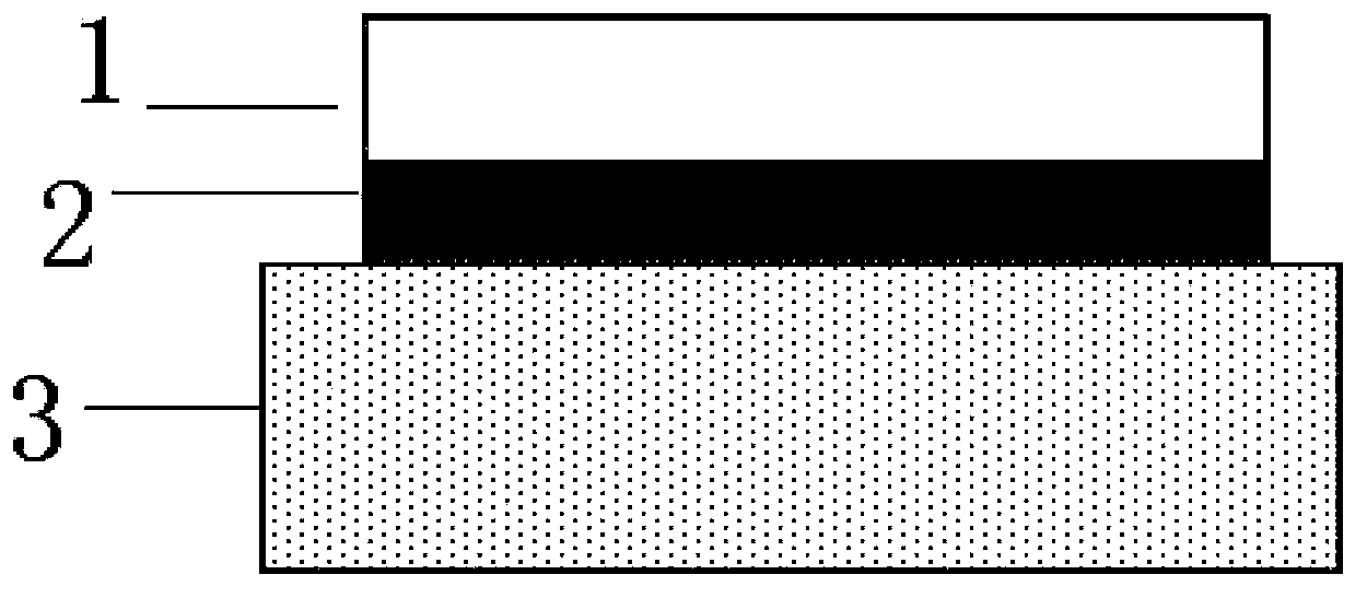
[0030] In this specific embodiment, a laser anti-reflection film design method with a non-uniform refractive index film layer, the laser anti-reflection film mainly includes a substrate, a high refractive index film layer, namely the H layer, and a low refractive index film layer, namely the L layer , choose the film material of H layer and L layer as Ta 2 o 5 and SiO 2 , the ideal physical model of the AR coating is as figure 1 shown. Include the following steps:

[0031] 1) Use an ellipsometer to measure the refractive index of the H layer and the L layer at the laser wavelength point;

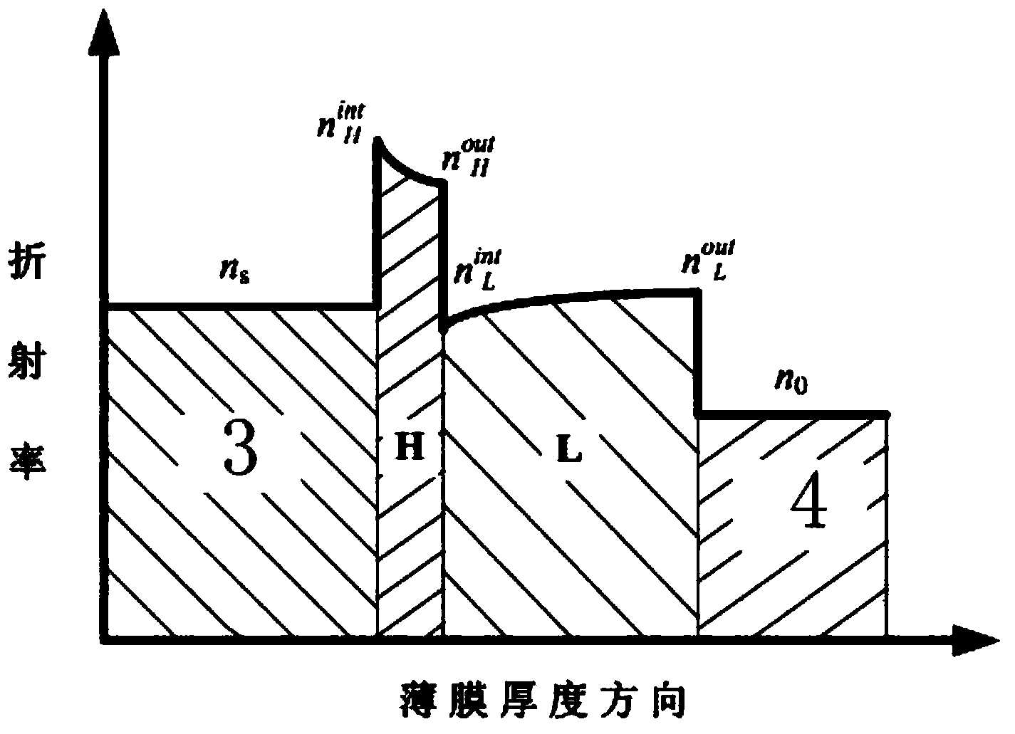
[0032] Measure the refractive index non-uniformity δH and δL of the H layer and L layer at the laser wavelength point;

[0033] Measure the refractive index of the H layer and the L layer at the proximal end and the far base ...


PUM

PropertyMeasurementUnit
wavelengthaaaaaaaaaa
angle of incidenceaaaaaaaaaa
thicknessaaaaaaaaaa

Abstract

The invention belongs to the technical field of vacuum film plating, and particularly to a designing method for an antireflection film for laser wavelength. The method comprises the following steps: 1) measuring refractive indexes of an H layer and an L layer through an ellipsometer; 2) computing physical thicknesses of the H layer and the L layer on an ideal setting condition; 3) setting the physical thickness space of the H layer to [(1-absolute value of (deltaH))dH,(1+absolute value of(deltaH)dH), and setting the physical thickness space of the L layer to [(1-absolute value of (deltaL)dL,(1+absolute value of (deltaL)Dl); 4) performing uniform layering on the H layer and the L layer; 5) discretizing the refractive indexes of an H layer and an L layer according to a preset layer number; 6) matrixing the thickness spaces of the H layer and the L layer, determining a step length according to control precision of depositing equipment, and computing residual refractive indexes in the physical thickness spaces; and 7) searching and determining a minimum point of the residual refractive indexes in a physical thickness matrix space, wherein the physical thickness layers of the corresponding H layer and the L layer are designed results.

Description

technical field [0001] The invention belongs to the technical field of vacuum coating, and in particular relates to a design method of a laser anti-reflection film. Background technique [0002] The single-wavelength anti-reflection coating used in laser systems generally adopts a structure with two layers of high and low refractive index materials with matching optical thickness. If the remaining reflectance of the anti-reflective coating is controlled below 0.01%, that is, when the transmittance reaches above 99.99%, ion beam sputtering deposition technology is generally used. The optical thin film prepared by this technology has the advantages of small absorption, small scattering of the film layer, high density, and improved surface roughness of the substrate, and is widely used in the preparation of laser thin films. [0003] However, the non-uniformity of the refractive index of the film prepared based on the ion beam sputtering deposition method is relatively obvious...

Claims


Application Information

Patent Timeline
Patent Type & Authority Applications(China)
IPC IPC(8): G02B1/11
Inventor 刘华松姜玉刚王利栓冷健季一勤
Owner THE 3RD ACAD 8358TH RES INST OF CASC
Why Eureka
Try Eureka