Optical imaging lens and electronic device using the lens
An optical imaging lens and lens technology, applied in optics, optical components, instruments, etc., can solve problems such as difficulty in conforming to miniaturization design trends, long overall length, etc., achieve good optical performance, shorten overall length, and expand half field of view corner effect
- Summary
- Abstract
- Description
- Claims
- Application Information
AI Technical Summary
Problems solved by technology
Method used
Image

Examples
no. 1 example
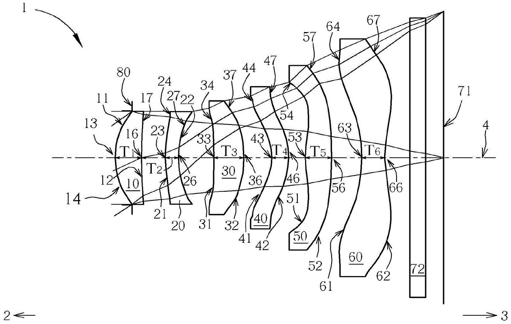
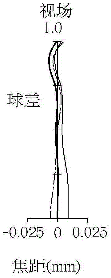
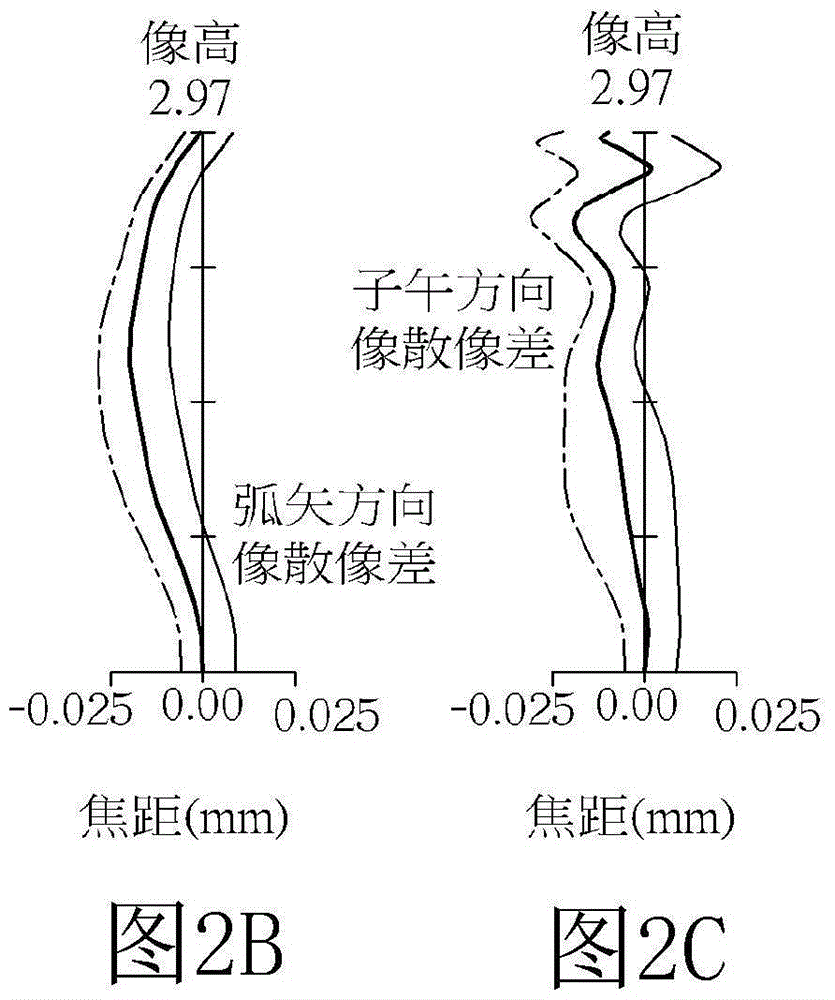
[0118] see figure 1 , illustrating the first embodiment of the optical imaging lens 1 of the present invention. For the longitudinal spherical aberration (longitudinal spherical aberration) on the imaging surface 71 of the first embodiment, please refer to Figure 2A , astigmatic field aberration in the sagittal direction, please refer to Figure 2B、Astigmatism aberration in the meridional direction (tangential) please refer to Figure 2C , and distortion aberration, please refer to Figure 2D . The Y-axis of each spherical aberration diagram in all embodiments represents the field of view, and its highest point is 1.0. In this embodiment, the Y-axis of each astigmatism diagram and distortion diagram represents the image height, and the system image height is 2.970 mm.
[0119] The optical imaging lens system 1 of the first embodiment is mainly composed of six lenses made of plastic and having refractive power, a filter 72 , an aperture 80 , and an imaging surface 71 . Th...
no. 2 example
[0138] see image 3 , illustrating the second embodiment of the optical imaging lens 1 of the present invention. For the longitudinal spherical aberration on the imaging surface 71 of the second embodiment, please refer to Figure 4A , Astigmatic aberration in the sagittal direction, please refer to Figure 4B 、Astigmatic aberration in the meridional direction, please refer to Figure 4C , Distortion aberration, please refer to Figure 4D . The concavo-convex shape of each lens surface in the second embodiment is substantially similar to the first embodiment, the difference lies in the parameters of the lens, such as the radius of curvature, the refractive index of the lens, the radius of curvature of the lens, the thickness of the lens, the aspheric coefficient of the lens or Back focus etc. are different. The detailed optical data of the second embodiment is as Figure 18 As shown, the aspheric data such as Figure 19 shown. The length of the optical imaging lens is ...
no. 3 example
[0141] see Figure 5 , illustrating the third embodiment of the optical imaging lens 1 of the present invention. For the longitudinal spherical aberration on the imaging surface 71 of the third embodiment, please refer to Figure 6A , Astigmatic aberration in the sagittal direction, please refer to Figure 6B 、Astigmatic aberration in the meridional direction, please refer to Figure 6C , Distortion aberration, please refer to Figure 6D . The concave-convex shape of each lens surface in the third embodiment is substantially similar to the first embodiment, the difference lies in the parameters of the lens, such as the radius of curvature, the refractive power of the lens, the radius of curvature of the lens, the thickness of the lens, the aspheric coefficient of the lens or Back focus etc. are different. The detailed optical data of the third embodiment are as Figure 20 As shown, the aspheric data such as Figure 21 As shown, the length of the optical imaging lens is ...
PUM
 Abstract
Description
Claims
Application Information
 - R&D
- Intellectual Property
- Life Sciences
- Materials
- Tech Scout
- Unparalleled Data Quality
- Higher Quality Content
- 60% Fewer Hallucinations
Browse by: Latest US Patents, China's latest patents, Technical Efficacy Thesaurus, Application Domain, Technology Topic, Popular Technical Reports.
© 2025 PatSnap. All rights reserved.Legal|Privacy policy|Modern Slavery Act Transparency Statement|Sitemap|About US| Contact US: help@patsnap.com