Imaging lens

Active Publication Date: 2007-03-29
TIANJIN OFILM OPTO ELECTRONICS CO LTD
View PDF0 Cites 33 Cited by
  • Summary
  • Abstract
  • Description
  • Claims
  • Application Information

AI Technical Summary

Benefits of technology

[0015] In the imaging lens according to one aspect of the invention, it is preferable that each of the first to fourth lenses includes at least one aspheric surface. Thus, high aberration performance can be obtained comparatively easily. When the first lens is composed of an optical lens and all the second to fourth lenses are composed of a resin material, reduction of various aberration

Problems solved by technology

However, the aspheric surfaces are disadvantageous in terms of manufacturing efficiency, and the cost is increased eas

Method used


Image

  • Imaging lens
  • Imaging lens
  • Imaging lens

Examples


Embodiment Construction

[0055] Although the invention will be described below with reference to the exemplary embodiments thereof, the following exemplary embodiments and modifications do not restrict the invention.

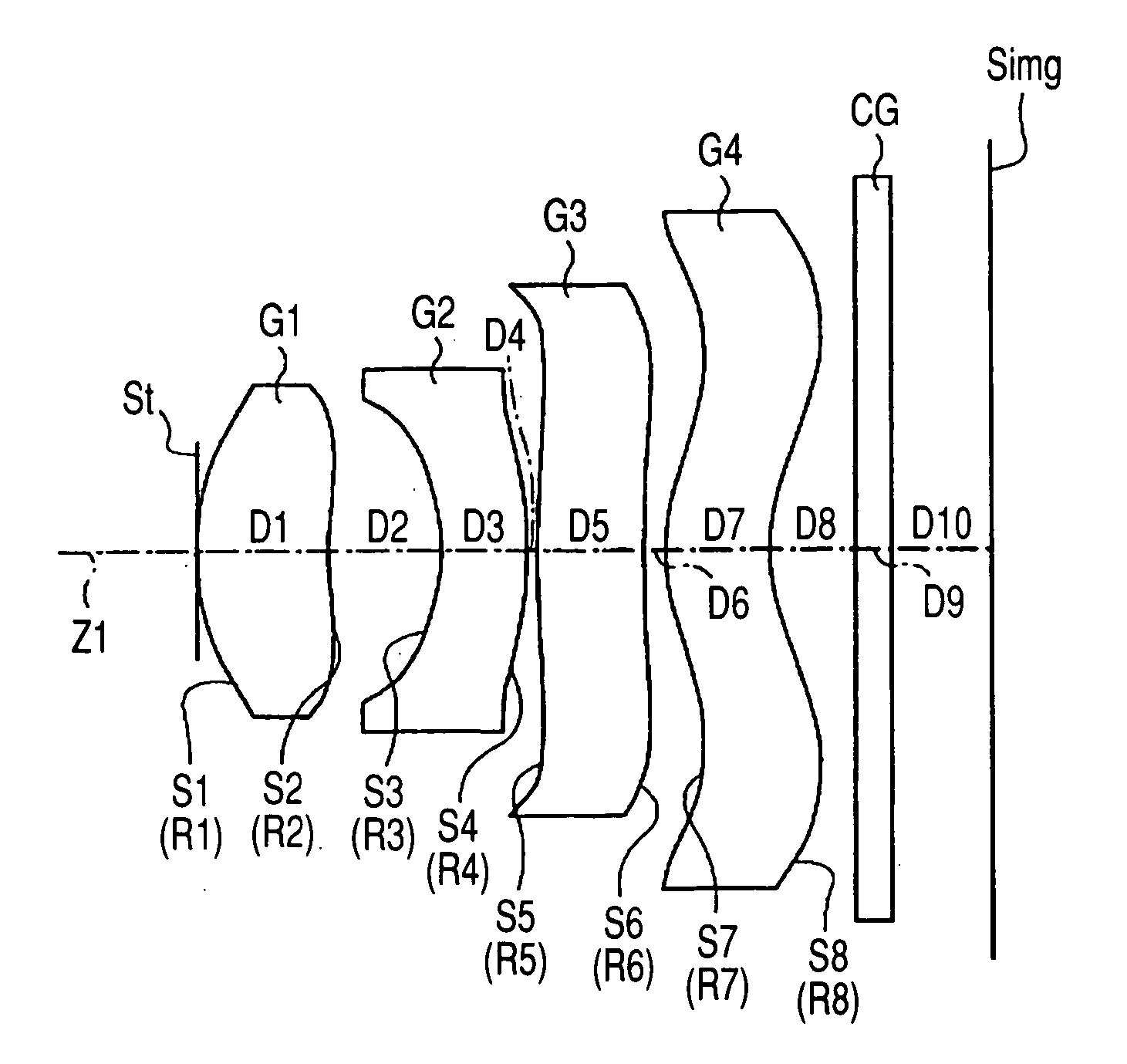
[0056] According to an exemplary embodiment, an imaging lens has a first lens having a convex surface on an object side and having a positive power, a second lens having a concave surface on the object side and having a negative power, a third lens having a positive power, and a fourth lens having a convex surface on the object side near a paraxial axis and having a meniscus shape. The first to fourth lenses are disposed in turn in order of increasing distance from an object. The imaging lens satisfies all the conditional expressions (1) to (5) so that the imaging lens can be made compact, and high resolution performance can be secured.

[0057] Exemplary embodiments of the invention will be described below in detail with reference to the drawings.

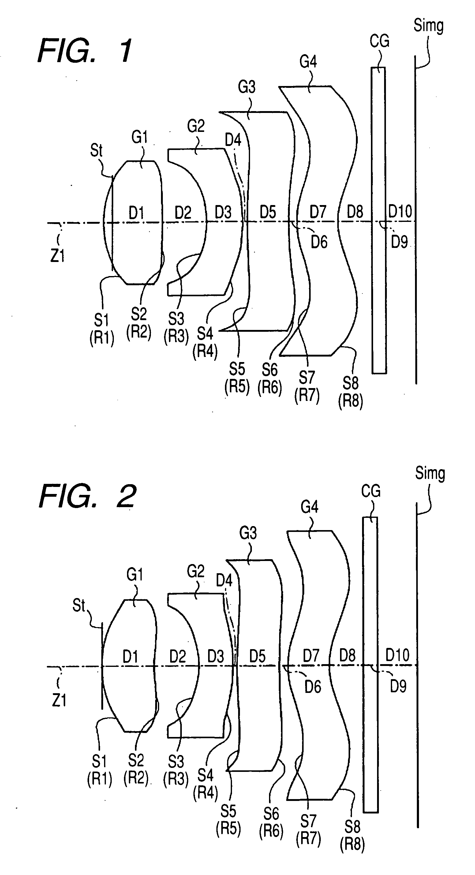
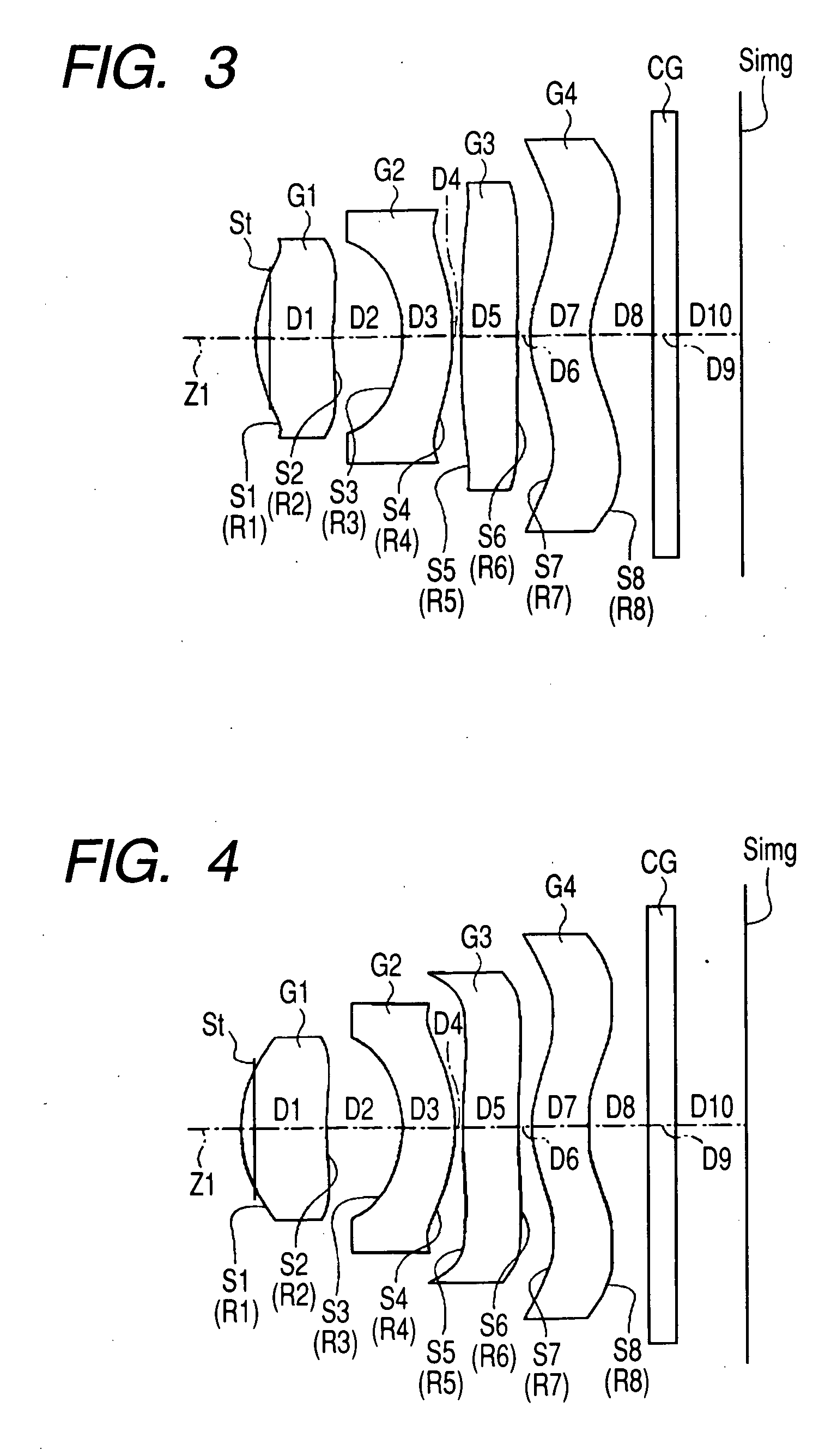
[0058]FIG. 1 shows a first configuration example...


PUM


Abstract

An imaging lens is provided and includes: in order from an object side of the imaging lens, a first lens having a convex surface on the object side and having a positive power; a second lens having a concave surface on the object side and having a negative power; a third lens having a positive power; and a fourth lens having a convex surface on the object side near a paraxial axis and having a meniscus shape. The imaging lens satisfies conditional expressions specified in the specification.

Description

BACKGROUND OF THE INVENTION [0001] 1. Field of the Invention [0002] The present invention relates to a fixed-focus imaging lens which can be suitably mounted on a small-sized imaging apparatus such as a digital camera using an image device such as a CCD (Charge Coupled Device) or a CMOS (Complementary Metal Oxide Semiconductor), a camera using a silver film, etc. [0003] 2. Description of Background Art [0004] In recent years, with the popularization of personal computers over general homes or the like, digital still cameras (hereinafter referred to as “digital cameras” simply) capable of inputting image information of photographed scenes, persons, etc. into personal computers have been coming into wide use rapidly. With the sophistication of cellular phones, module cameras (portable module cameras) for inputting images have been often mounted on cellular phones. [0005] In such an imaging apparatus, an imaging device such as a CCD or a CMOS is used. With recent development in miniatu...

Claims


Application Information

Patent Timeline
IPC IPC(8): G02B9/34
CPCG02B13/004G02B9/34G02B13/18
Inventor TANIYAMA, MINORU
Owner TIANJIN OFILM OPTO ELECTRONICS CO LTD
Why Eureka
Try Eureka