Projection Lens and Projector With Magnifying Function

a technology which is applied in the field of projection lens and projector with magnifying function, can solve the problems of lens not being said to be suited for projectors, lens size increase of projection lenses, and significant magnification chromatic aberration, etc., and achieves high magnification ratio, high aberration performance, and reduced size

Active Publication Date: 2016-06-02
KONICA MINOLTA INC
View PDF1 Cites 12 Cited by
  • Summary
  • Abstract
  • Description
  • Claims
  • Application Information

AI Technical Summary

Benefits of technology

[0007]The present invention has been made in view of the foregoing circumferences. An object of the present invention is to provide a projection lens that has high aberration performance and high magnification ratios corresponding to high-definition image display elements and achieves size reduction, and a projector including the projection lens.

Problems solved by technology

In the case of enlarging and projecting an image, the magnification chromatic aberration becomes significantly prominent, and the lenses cannot be said to be suited for projectors.
When an attempt is made to achieve a high magnification ratio while correcting favorably the magnification chromatic difference, the amounts of movement of the respective lens groups become large to result in size increase of the projection lenses.

Method used


Image

  • Projection Lens and Projector With Magnifying Function
  • Projection Lens and Projector With Magnifying Function
  • Projection Lens and Projector With Magnifying Function

Examples


examples

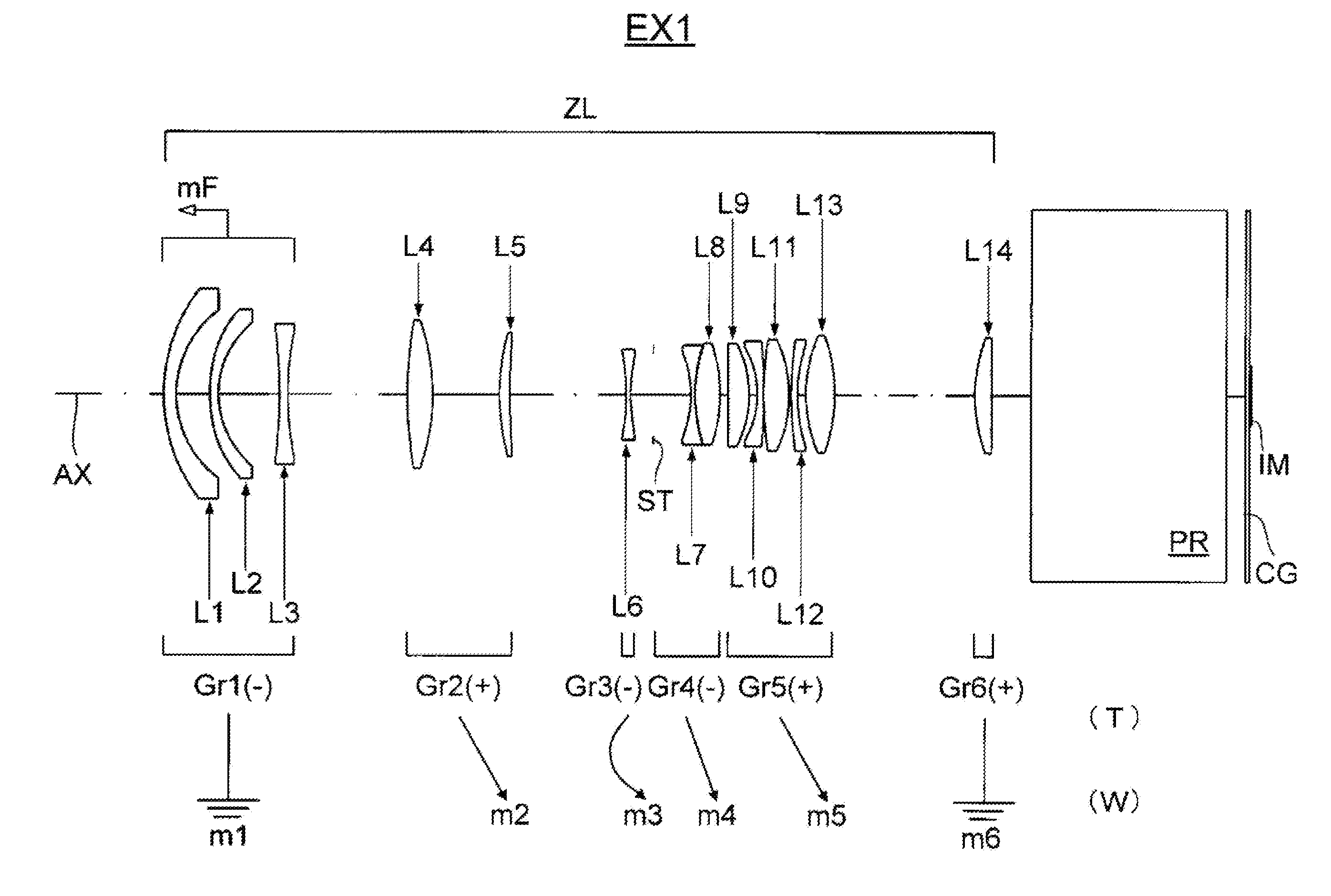
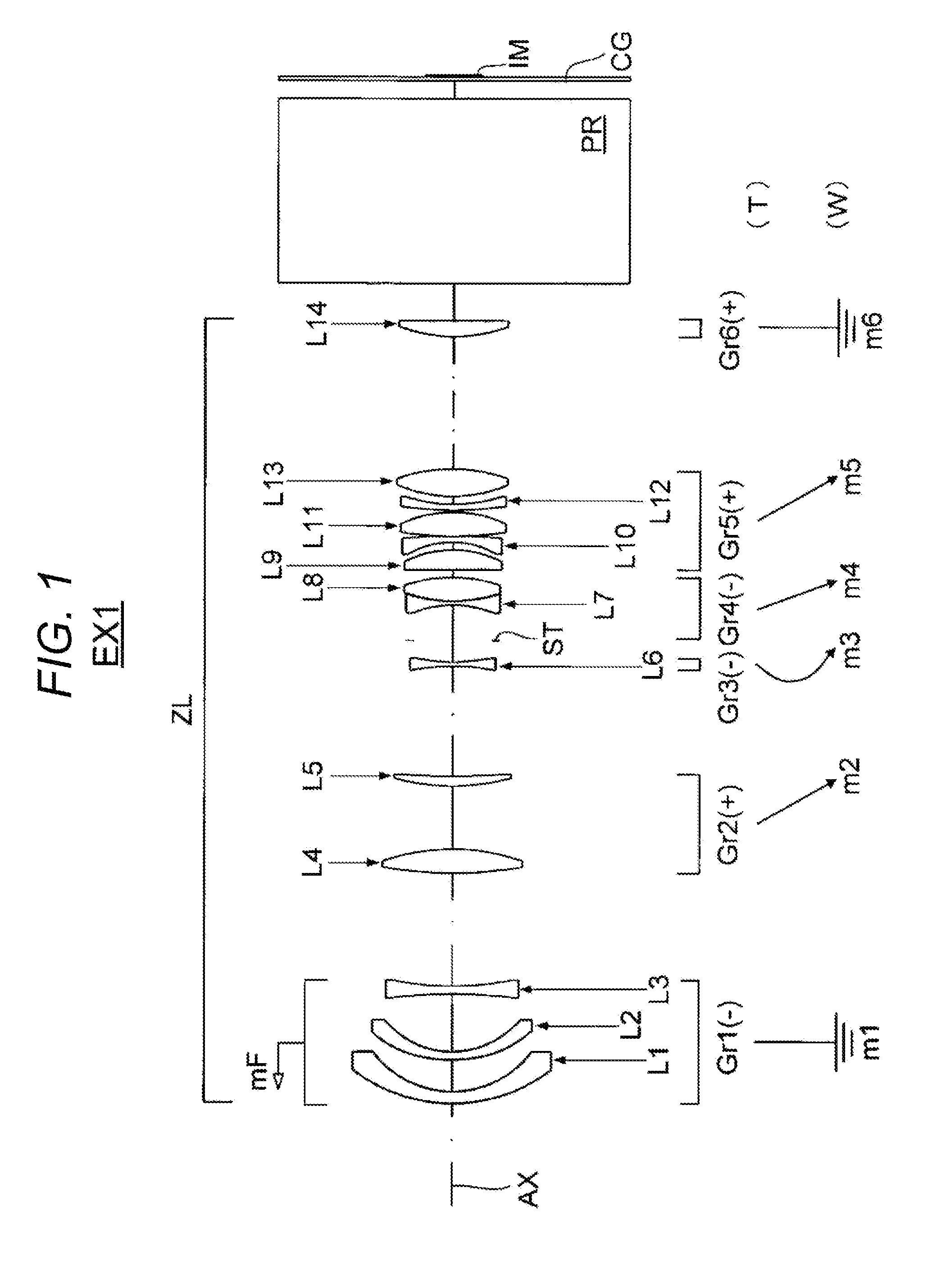
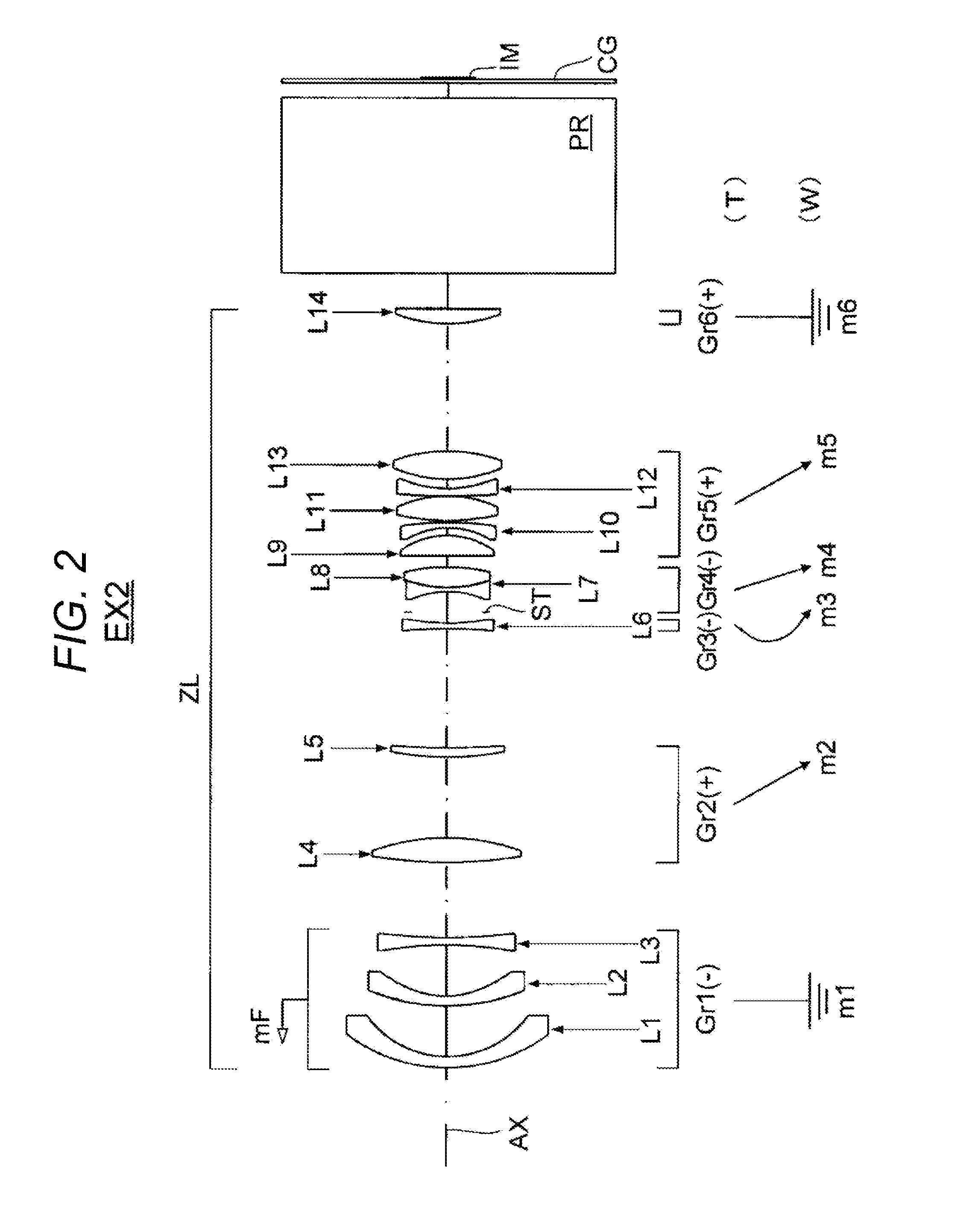
[0089]Configuration examples and the like of the projection lens in which the present invention is carried out will be further specifically described with construction data and the like of examples. Examples 1 to 5 (EX1 to EX5) taken herein are numerical examples corresponding to the first to fifth embodiments, respectively. Lens configuration diagrams (FIGS. 1 to 5) representing Examples 1 to 5 illustrate lens cross-section shapes, lens layouts, and others in the corresponding to Examples 1 to 5, respectively.

[0090]The respective construction data in the examples includes, as surface data, surface number i, curvature radius CR (mm), axial inter-surface distance d (mm), refractive index nd relative to d line (wavelength of 587.56 nm), and abbe number υd relative to d line, in sequence from the leftmost column. In the surface data, Lj / Grk indicates the applicable j-th lens Lj and k-th lens group Grk, ST the aperture stop, and IM the image display surface.

[0091]The surfaces with surfa...

example 1

[0134]

Unit: mmSurface dataiCRdndνd 149.363.081.7640.10(L1 / Gr1) 229.249.37 3*53.212.791.4957.49(L2 / Gr1) 4*28.8616.49  5−171.332.321.8337.34(L3 / Gr1) 6105.14Variable 7166.776.671.5264.20(L4 / Gr2) 8−63.7218.45  963.223.271.7943.93(L5 / Gr2)10217.08Variable11−78.661.421.5081.61(L6 / Gr3)1268.64Variable13∞10.07 (ST / Gr4)14−33.741.421.6263.39(L7 / Gr4)1543.280.011.5547.001643.286.731.6931.16(L8 / Gr4)17−48.65Variable18581.315.891.5081.61(L9 / Gr5)19−31.422.3020−27.371.571.9135.25(L10 / Gr5)21−422.470.3522105.157.031.5081.61(L11 / Gr5)23−35.230.2024100.451.751.9532.32(L12 / Gr5)2538.802.652645.127.661.5081.61(L13 / Gr5)27−60.38Variable2853.464.481.5081.61(L14 / Gr6)29−744.5711.00 30∞54.00 1.5264.20(PR)31∞5.0032∞1.051.4970.44(CG)33∞0.7034 (IM)Aspheric surface dataiKA4A6A8A1030.0000E+001.4981E−05−1.3607E−08−1.2727E−113.3770E−1440.0000E+001.1162E−05−5.5526E−09−7.5972E−111.1372E−13Various dataTELEMIDDLEWIDEFocal length25.4118.0012.70Zoom ratio2.00Image height8.50Half angle ω18.4925.2833.79F number2.532.252.00BF53.01...

example 2

[0135]

Unit: mmSurface dataiCRdndνd 153.243.291.7640.10(L1 / Gr1) 231.2415.87  366.652.891.5356.38(L2 / Gr1) 4*27.9315.37  5−124.282.511.6747.20(L3 / Gr1) 6186.38Variable 7147.917.551.5264.20(L4 / Gr2) 8−69.6924.71  972.153.231.7943.93(L5 / Gr2)10314.09Variable11−85.431.581.5081.61(L6 / Gr3)1278.99Variable13∞6.31(ST / Gr4)14−33.301.351.6263.39(L7 / Gr4)1536.180.011.5547.001636.186.601.6732.17(L8 / Gr4)17−56.25Variable18−817.816.151.5081.61(L9 / Gr5)19−27.322.7120−23.141.541.8337.34(L10 / Gr5)21−86.210.752269.757.481.5081.61(L11 / Gr5)23−37.330.2524258.691.731.8337.34(L12 / Gr5)2533.443.232642.068.801.5081.61(L13 / Gr5)27−49.47Variable2853.094.281.5081.61(L14 / Gr6)29∞11.00 30∞54.00 1.5264.20(PR)31∞5.0032∞1.051.4970.44(CG)33∞0.7034 (IM)Aspheric surface dataiKA4A6A8A1040.0000E+00−5.4843E−06−8.1259E−095.8833E−12−1.6062E−14Various dataTELEMIDDLEWIDEFocal length25.4517.9712.72Zoom ratio2.00Image height8.50Half angle ω18.4725.3233.75F number2.562.302.00BF53.01Entire lens length235.00φ34−0.01593−0.01727−0.01772Inter-gro...


PUM


Abstract

A projection lens includes a first lens group having negative refractive power, a second lens group having positive refractive power, a third lens group having negative refractive power, a fourth lens group having negative refractive power, a fifth lens group having positive refractive power, and a sixth lens group having positive refractive power, in sequence from an enlargement conjugate side, the projection lens performing magnification by changing the spacing between the lens groups, wherein at the time of magnification from the telephoto end to the wide-angle end, the second, third, fourth, and fifth lens groups are moved, and an aperture stop is arranged between the surface of the third lens group closest to a reduction conjugate side and the surface of the fifth lens group closest to the enlargement conjugate side.

Description

[0001]The entire disclosure of Japanese Patent Application No. 2014-242977 filed on Dec. 1, 2014 including description, claims, drawings, and abstract are incorporated herein by reference in its entirety.BACKGROUND OF THE INVENTION[0002]1. Field of the Invention[0003]The present invention relates to a projection lens and a projector with a magnifying function. For example, the present invention relates to a wide-viewing-angle projection zoom lens suited to enlarge and project an image displayed on an image display element such as a digital micromirror device or an LCD (liquid crystal display) onto a screen, and a projector including the same.[0004]2. Description of the Related Art[0005]JP 2004-117519 A and JP 2005-106948 A propose zoom lenses suitable as projection lenses for projector. The zoom lenses described in JP 2004-117519 A and JP 2005-106948 A have four groups with negative, positive, negative, and positive lenses, five groups with negative, positive, negative, positive, an...

Claims


Application Information

Patent Timeline
Patent Type & Authority Applications(United States)
IPC IPC(8): G02B15/177G02B13/16G02B13/18G02B13/04
CPCG02B15/177G02B13/18G02B13/16G02B13/04G02B15/1465
Inventor IMAI, YUSUKEINOUE, KAZUHIKO
Owner KONICA MINOLTA INC
Why Eureka
Try Eureka