
Imaging lens

a fixed-focus, imaging lens technology, applied in the field of imaging lenses, can solve problems such as increasing costs, and achieve the effects of shortening the full length, ensuring the telecentric property easily, and improving the correction of lateral color

Active Publication Date: 2007-09-20
TIANJIN OFILM OPTO ELECTRONICS CO LTD
View PDF1 Cites 16 Cited by
  • Summary
  • Abstract
  • Description
  • Claims
  • Application Information

AI Technical Summary

Benefits of technology

[0010]An object of an illustrative, non-limiting embodiment of the present invention is to provide an imaging lens for providing high image formation performance while the imaging lens has a more compact configuration.
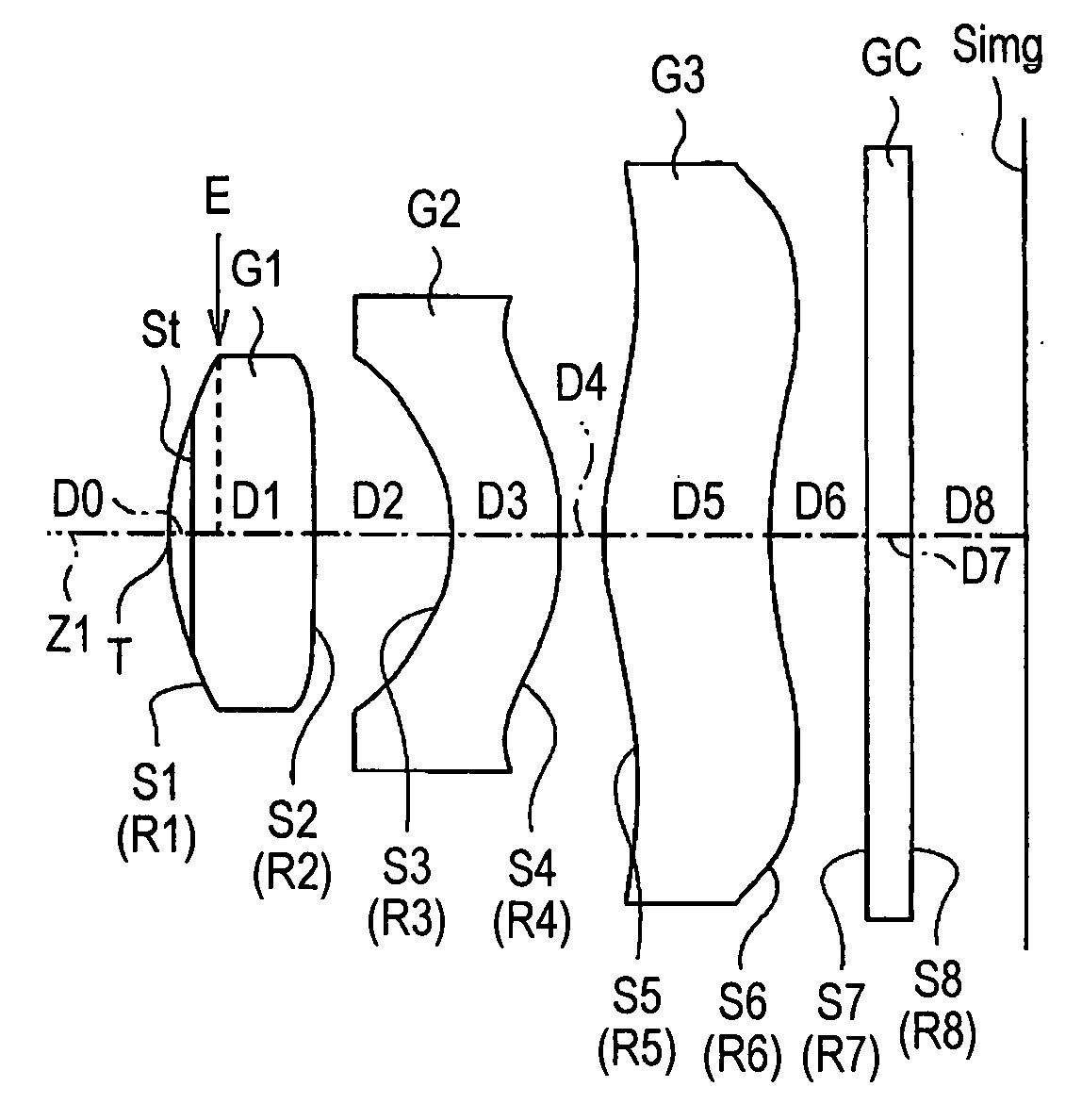
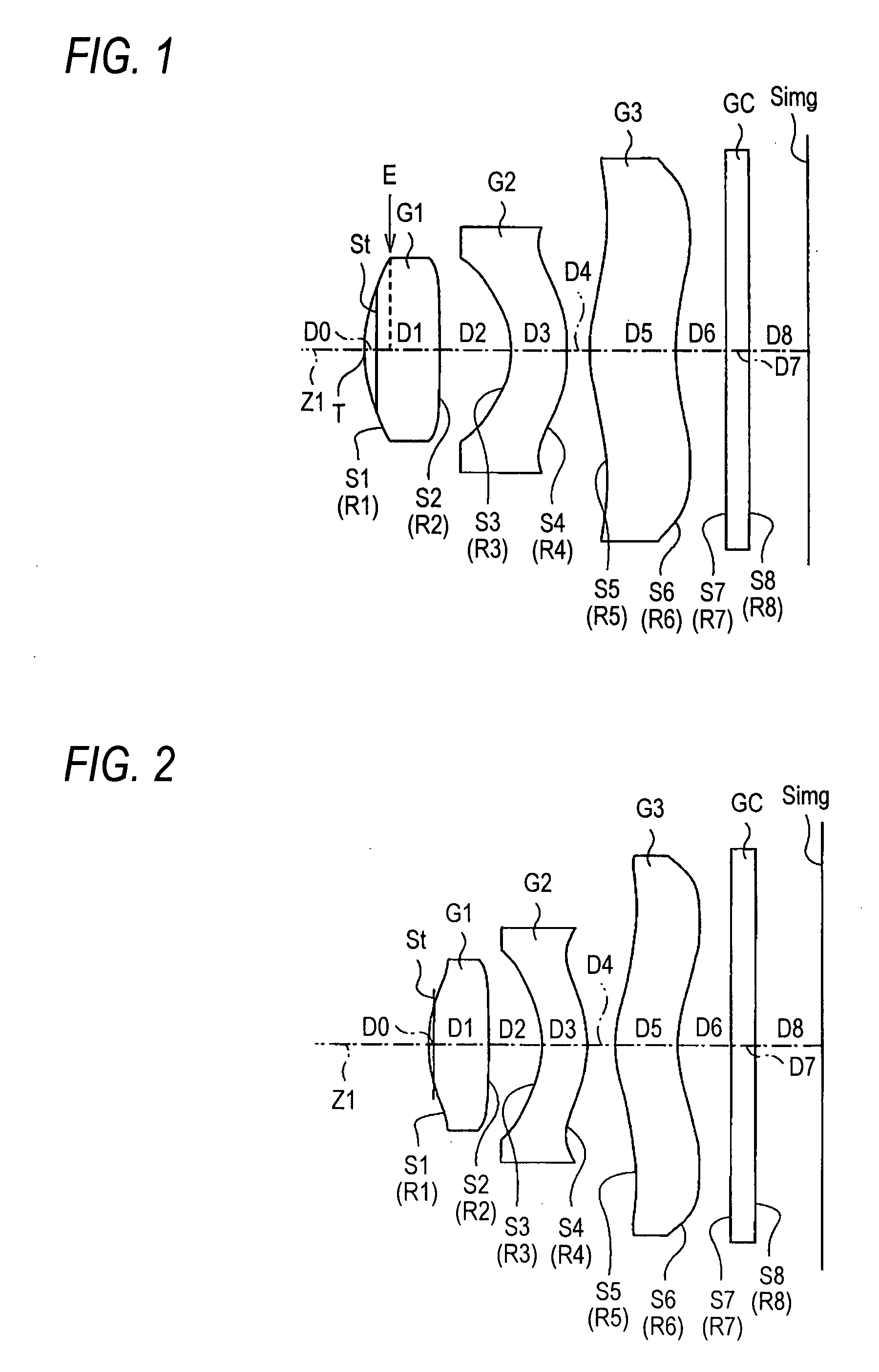
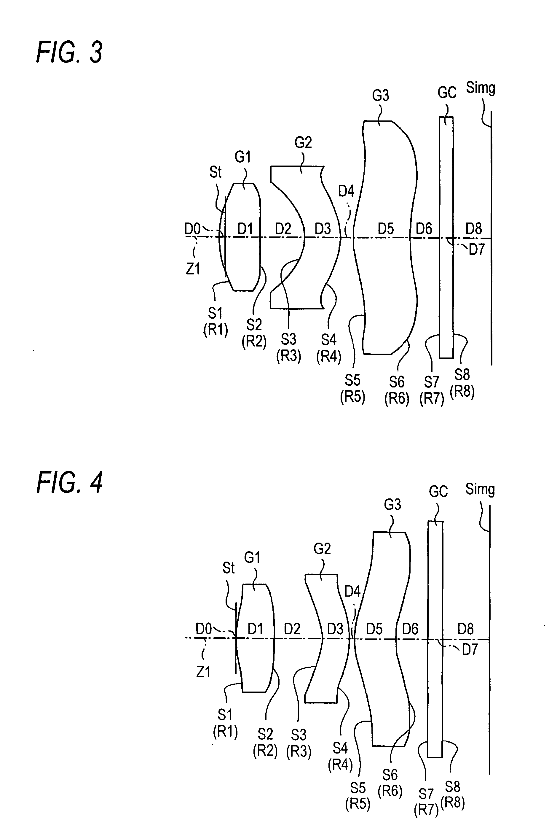
[0012]An imaging lens according to an aspect of the invention is compacted as it is made up of a small number of lenses (three), and provides high image formation performance compatible with a digital camera installing an imaging device with a large number of pixels. Specifically, since the first lens has such power satisfying conditional expression (1), upsizing is suppressed and an increase in spherical aberration is also suppressed. The object-side surface of the first lens has such a shape satisfying conditional expression (2), whereby field curvature is well corrected. Since the second lens has such power satisfying conditional expression (3), high-order aberration of spherical aberration, coma aberration, etc., is well corrected. The aperture diaphragm is placed between the top position of the object-side surface of the first lens and the position of the image-side surface of the first lens on the optical axis, so that compatibility between ensuring of telecentric property and lessening of the effect of mutual axis shift in the first lens to the third lens on the optical performance (axis shift sensitivity) can be provided and in addition, there is also an advantage for shortening the full length of the imaging lens.
[0017]In the imaging lens, the aperture diaphragm may be placed between the top position of the object-side surface of the first lens and an edge position of the object-side surface of the first lens on the optical axis. In so doing, the angle of the emission light ray toward the image formation surface can lessen, so that the telecentric property is ensured easily. It is advantageous for shortening the full length as compared with the case where the aperture diaphragm is placed to the object side than the top position of the object-side surface of the first lens on the optical axis.
[0018]In the imaging lens, each of the first, second, and third lenses may contain at least one aspheric surface. In so doing, high aberration performance can be provided comparatively easily. If the first lens is formed of optical glass and the second lens and the third lens are formed of a resin material, slimming down as well as a decrease in the aberrations and distortion (particularly lateral color) can be realized.

Problems solved by technology

However, adopting an aspheric surface is disadvantageous for manufacturability and easily results in an increase in the cost although it contributes to compaction and higher performance.
The lenses described in the documents above adopt a three-lens configuration and use an aspheric surface, but are insufficient from the viewpoint of compatibility between the image formation performance and compactibility.

Method used


Image

  • Imaging lens
  • Imaging lens
  • Imaging lens

Examples


Embodiment Construction

[0049]Although the invention will be described below with reference to the exemplary embodiments thereof, the following exemplary embodiments and modifications do not restrict the invention.

[0050]According to an exemplary embodiment, a positive first lens having a convex surface directed to the object side on the optical axis, a second lens having a meniscus shape with a concave surface directed to the object side on the optical axis, and the third lens having a meniscus shape with a convex surface directed to the object side on the optical axis are placed in order from the object side, an aperture diaphragm is placed between a position of the object-side surface of the first lens and a position of the image-side surface of the first lens on the optical axis, and conditional expressions (1) to (3) are all satisfied, so that while the aberrations of spherical aberration, field curvature, coma aberration, etc., are well corrected and high image formation performance is provided, compa...


PUM


Abstract

An imaging lens is provided and includes: in order from an object side of the imaging lens, a first lens having a convex surface directed to the object side on an optical axis and having a positive power; an aperture diaphragm placed between a top position of an object-side surface of the first lens and a position of an image-side surface of the first lens on the optical axis; a second lens having a meniscus shape with a concave surface directed to the object side on the optical axis; and a third lens having a meniscus shape with a convex surface directed to the object side on the optical axis. Further, the imaging lens satisfies specific conditional expressions.

Description

BACKGROUND OF THE INVENTION[0001]1. Field of the Invention[0002]This invention relates to a fixed-focus imaging lens suited to installation in a small-sized imaging apparatus such as a digital camera using an imaging device of a CCD (Charge Coupled Device), a CMOS (Complementary Metal Oxide Semiconductor), etc., or a cameral using a silver film.[0003]2. Description of Related Art[0004]In recent years, a digital still camera (hereinafter simply referred to as “digital camera”) for enabling image information of a photographed landscape, portrait, etc., to be input to a personal computer has sprung into wide use with the widespread proliferation of a personal computer into ordinary households, etc. A module camera for image input (mobile module camera) has often been installed in a mobile telephone with higher functionality of a mobile telephone.[0005]In the imaging apparatus, an imaging device of a CCD, a CMOS, etc., is used. Such an imaging apparatus has been very miniaturized as the...

Claims


Application Information

Patent Timeline
Patent Type & Authority Applications(United States)
IPC IPC(8): G02B9/14
CPCG02B13/0035G02B9/16
Inventor TANIYAMA, MINORU
Owner TIANJIN OFILM OPTO ELECTRONICS CO LTD
Learn More