
Imaging lens

a technology of imaging and lens, applied in the field of imaging lenses, can solve the problems of reducing size, shutter mechanism, etc., and achieve the effects of increasing the number of pixels, optimizing the shape and refractive power of each lens, and high aberration performan

Active Publication Date: 2007-10-04
TIANJIN OFILM OPTO ELECTRONICS CO LTD
View PDF13 Cites 1 Cited by
  • Summary
  • Abstract
  • Description
  • Claims
  • Application Information

AI Technical Summary

Benefits of technology

[0006]The invention has been made in view of these circumstances and provides a small-sized and high-performance imaging lens which can ensure sufficiently an internal interval where the shutter mechanism is disposed, while maintaining high aberration performance compatible with increase in number of pixels.
[0008]With this configuration, since a shapes and a refractive force of each lens are optimized in the lens configuration having few lenses, that is, three lenses as a whole, a reduction in size can be attained. Also, since the conditional expression (2) is satisfied, the interval between the first lens and the second lens can be widely ensured. This configuration is advantageous in arranging the shutter mechanism. Also, since the shape of the first lens has the biconvex shape in the vicinity of the optical axis, it is easy to ensure the interval where the shutter mechanism is disposed in rear of the first lens in comparison with the case where the surface of the first lens on the image side has a concave shape. Also, since the conditional expression (1) is satisfied, a power distribution of the first lens is optimized and the high aberration performance compatible with the increase in the number of pixels is maintained.
[0009]Also, the following conditional expression may be further satisfied. With this configuration, a power balance between the second lens and the third lens is optimized and a high performance is easily achieved.0.3<|f2 / f|<1.00.5<f3 / f<1.0where f2 denotes a focal length of the second lens and f3 denotes a focal length of the third lens.
[0011]Also, the second lens may have a biconcave shape in a vicinity of the optical axis. With this configuration, the respective conditional expressions are easily satisfied, and the higher performance is easily attained.
[0013]According to the imaging lens of the invention, the lens configuration having few lenses, that is, the three lenses as a whole is made to satisfy the predetermined conditional expressions so as to optimize the shape and the refractive power of each lens and arrangement of each lens. Therefore, the invention can realize the small-sized and high-performance lens system capable of ensuring the sufficient internal interval where the shutter mechanism is disposed, while maintaining the high aberration performance compatible with the increase in the number of pixels.

Problems solved by technology

However, it is disadvantageous in size reduction that the shutter mechanism is arranged on the most-object side, e.g., in front of the first lens.

Method used


Image

  • Imaging lens
  • Imaging lens
  • Imaging lens

Examples


examples

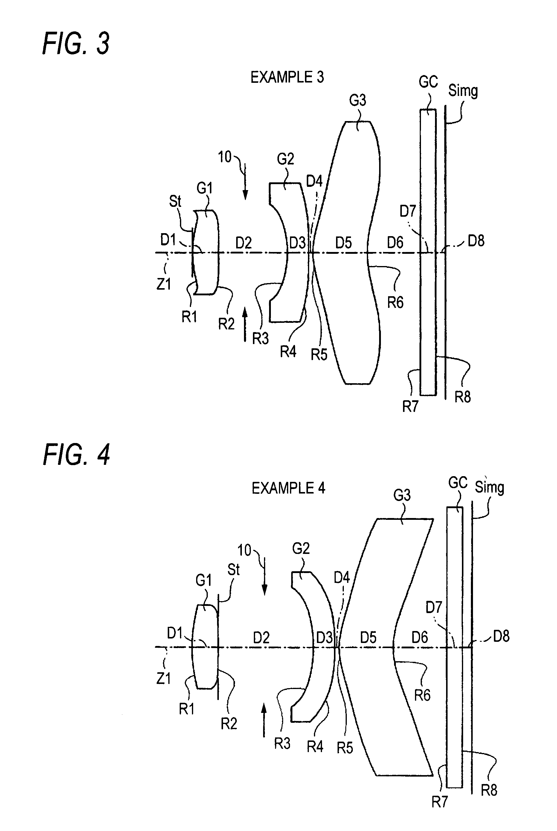
[0055]Next, specific numerical examples of the imaging lens according to this embodiment will be described hereunder. First to seventh numerical examples will be described collectively in the following.

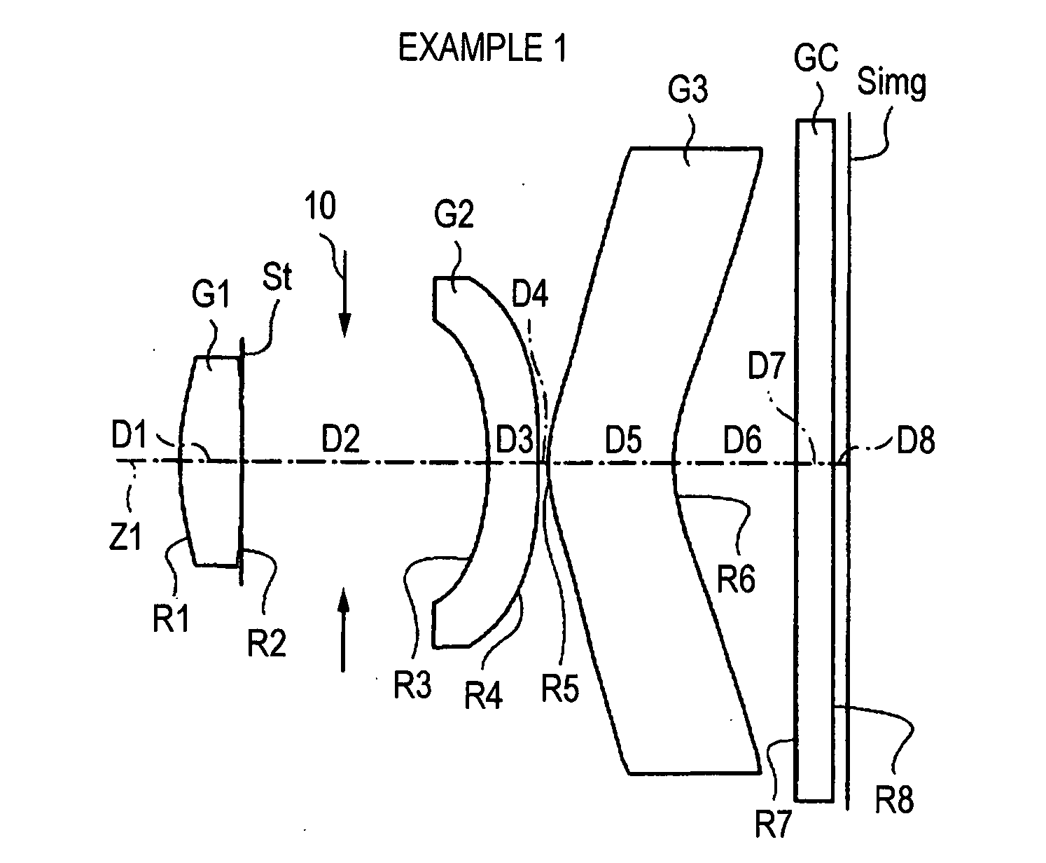
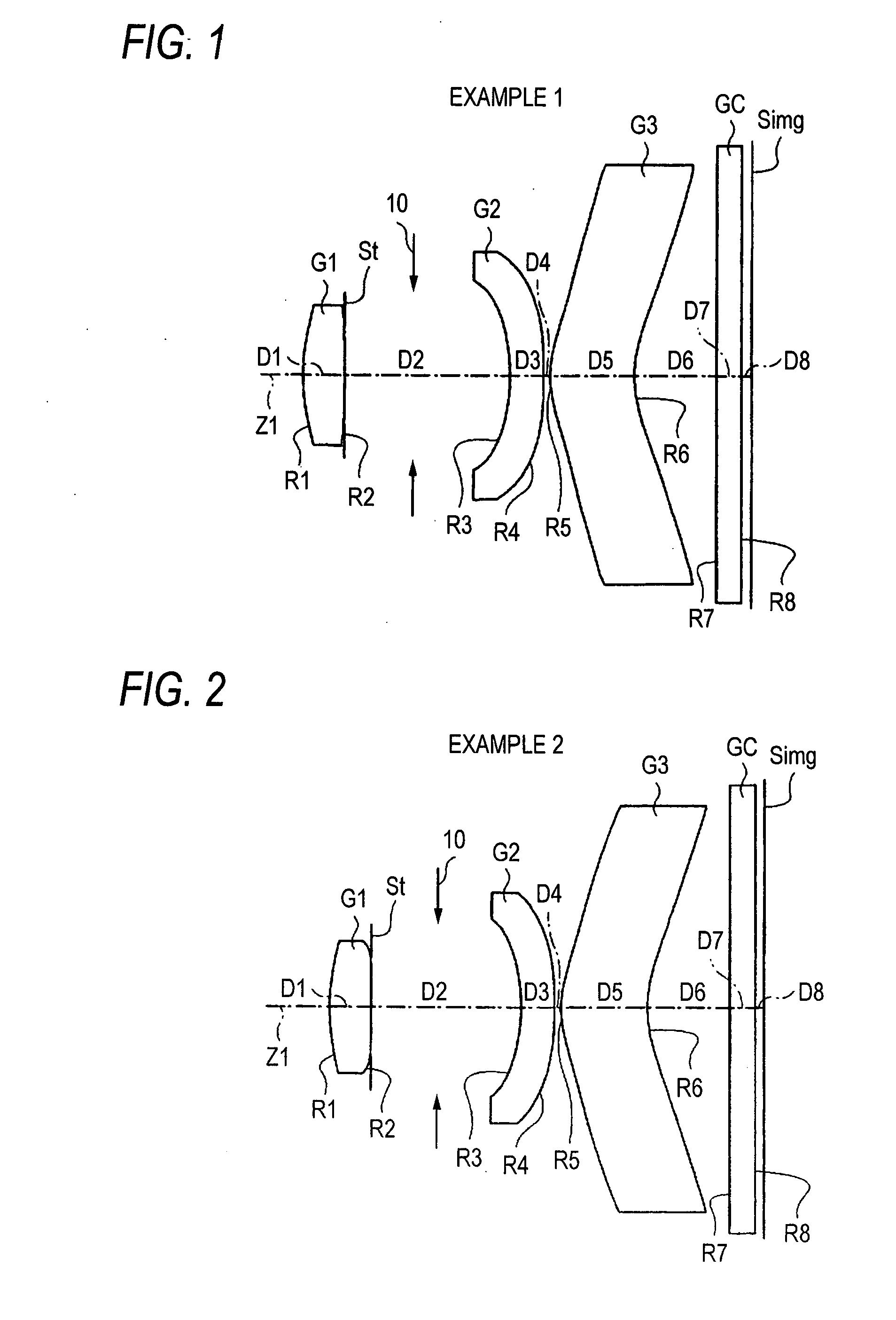
[0056]Specific lens data corresponding to the configuration of the imaging lens shown in FIG. 1 are shown as an example 1 in FIGS. 8A and 8B. In particular, basic lens data are shown in FIG. 8A, and data regarding the aspheric surface are shown in FIG. 8B. A column of a surface number Si in the lens data shown in FIG. 8A shows number of i-th (I=1 to 8) surface in such a manner that the surface of the constituent element located on the most-object side is set to the first surface and the surface number is increased sequentially as advancing to the image side. A column of a radius of curvature Ri shows values (mm) of a radius of curvature of an i-th surface from the object side to correspond to a radius of curvature Ri shown in FIG. 1. A column of a surface interval Di shows intervals (...


PUM


Abstract

An imaging lens includes first to third lenses G1 to G3 arranged in order from a object side. The first lens has a biconvex shape in a vicinity of an optical axis Z1. The second lens has a concave surface facing a object side. The second lens has a negative refractive power. The third lens has a positive or negative refractive power and has a meniscus shape containing, in a vicinity of the optical axis, a convex surface facing the object side. The following conditional expression is satisfied:0.7<f1 / f<1.30.2<D2 / f<0.5where f denotes a focal length of the entire system of the imaging lens, f1 denotes a focal length of the first lens G1 and D2 denotes an interval on the optical axis Z1 between the first lens G1 and the second lens G2.

Description

BACKGROUND OF THE INVENTION[0001]1. Technical Field[0002]The invention relates to an imaging lens mounted on an imaging device, such as a digital still camera, a cellular phone with camera, PDA (Personal Digital Assistance), including an imaging element such as a CCD (Charge Coupled Device) and a CMOS (Complementary Metal Oxide Semiconductor).[0003]2. Description of the Related Art[0004]In the field of an imaging element such as CCD and CMOS, a reduction in size and an increase in numbers of pixel are proceeding greatly nowadays. Therefore, a small and high performance type is required for an imaging device itself and lenses mounted on the imaging device. For the purpose of a reduction in size, reduction in a total length and reduction in height (size reduction in the diameter direction perpendicular to the optical axis) are required. Also, normally the telecentric property, i.e., an incident angle of the principal ray to the imaging element should be set closely in parallel to the ...

Claims


Application Information

Patent Timeline
Patent Type & Authority Applications(United States)
IPC IPC(8): G02B9/14
CPCG02B9/12G02B13/0035G02B9/16
Inventor SATO, KENICHITANIYAMA, MINORU
Owner TIANJIN OFILM OPTO ELECTRONICS CO LTD
Learn More