Imaging lens

a technology of imaging lens and focusing lens, which is applied in the field of imaging lens, can solve the problems of easy increase of manufacturing cost, increase of number of pixels included in imaging device, and increase in cost performance and compactness, and achieve the effects of reducing various aberrations, reducing the weight of imaging lens, and high aberration performan

Active Publication Date: 2007-12-20
TIANJIN OFILM OPTO ELECTRONICS CO LTD
View PDF8 Cites 1 Cited by
  • Summary
  • Abstract
  • Description
  • Claims
  • Application Information

AI Technical Summary

Benefits of technology

[0015]Further, each of the first, second, third and fourth lenses may have at least one aspheric surface. This makes it easy to obtain a high aberration performance. Also, the first lens may be made of an optical glass, while each of the second, third and fourth lenses may be made of a resin material. This provides an advantage in reducing various aberrations (especially, chromatic aberration) and also can realize the reduced weight of the imaging lens.

Problems solved by technology

On the other hand, with respect to the imaging lens for a module camera for a cellular phone, there have been mainly required cost performance and compactness; however, recently, in the module camera for a cellular phone as well, the number of pixels included in the imaging device has been increasing and thus the need for the enhanced performance of the module camera for a cellular phone has been increasing.
In this case, the aspherical surface contributes to the downsizing and enhanced performance, but it provides a disadvantage in manufacture and thus their manufacturing costs are easy to increase.
However, in this lens configuration, for example, the image forming performance and compactness do not go together sufficiently.
However, from the before-mentioned viewpoint, when the aperture diaphragm and shutter mechanism are disposed nearer to the object side than a first lens, the whole length of the lenses is large, which provides a disadvantage in downsizing the imaging device.

Method used


Image

  • Imaging lens
  • Imaging lens
  • Imaging lens

Examples


Embodiment Construction

to 6, corresponding to conditional expressions (1) to (7);

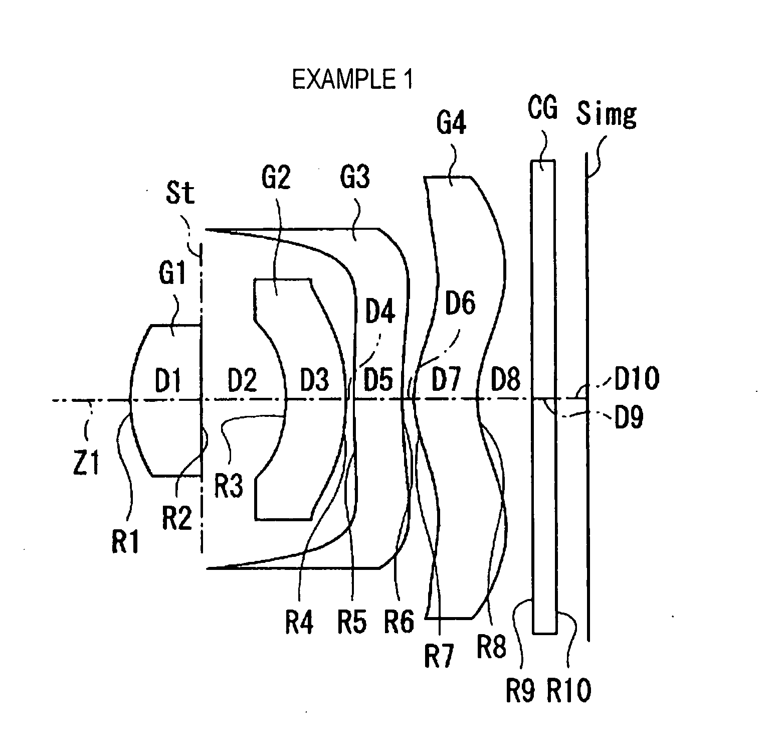
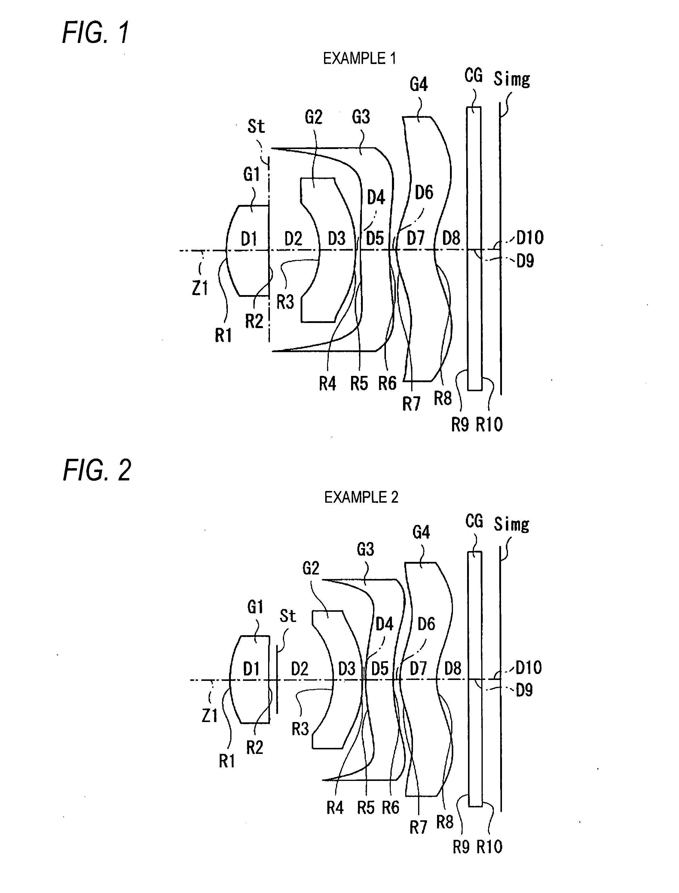
[0036]FIGS. 20A to 20C show aberrations in the imaging lens according to Example 1, FIG. 20A shows the spherical aberration, FIG. 20B shows the astigmatism, and FIG. 20C shows distortion;

[0037]FIGS. 21A to 21C show aberrations in the imaging lens according to Example 2, FIG. 21A shows the spherical aberration, FIG. 21B shows the astigmatism, and FIG. 21C shows distortion;

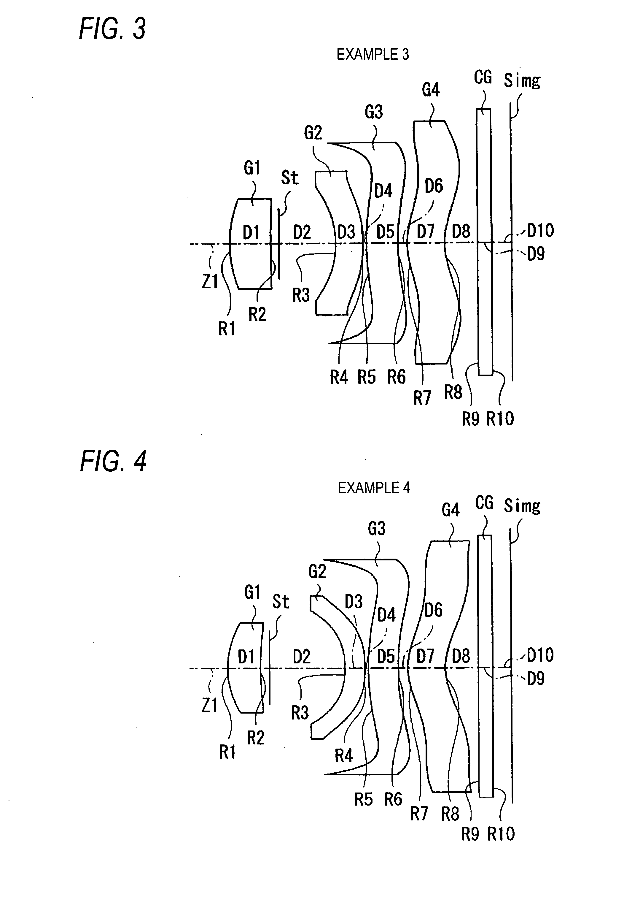
[0038]FIGS. 22A to 22C show aberrations in the imaging lens according to Example 3, FIG. 22A shows the spherical aberration, FIG. 22B shows the astigmatism, and FIG. 22C shows distortion;

[0039]FIGS. 23A to 23C show aberrations in the imaging lens according to Example 4, FIG. 23A shows the spherical aberration, FIG. 23B shows the astigmatism, and FIG. 23C shows distortion;

[0040]FIGS. 24A to 24C show aberrations in the imaging lens according to Example 5, FIG. 24A shows the spherical aberration, FIG. 24B shows the astigmatism, and FIG. 24C shows distortion; and...


PUM


Abstract

An imaging lens is provided and includes: in order from the object side, a first lens having a convex surface on the object side and having a positive power; an aperture diaphragm; a second lens having a concave surface on the object side and having a negative power; a third lens having a positive power; and a fourth lens having a convex surface on the object side near the optical axis, the fourth lens having a meniscus shape. The imaging lens satisfies conditional expressions:
0.2<D2/f<0.4   (1)
TL/f<1.3   (2)
where f represents a focal distance of the imaging lens; D2 represents an air interval between the first lens and second lens along an optical axis of the imaging lens; and TL represents a distance (along the optical axis) from an object-side surface of the first lens to an image forming surface.

Description

BACKGROUND OF THE INVENTION[0001]1. Field of the Invention[0002]The present invention relates to an imaging lens having a fixed focus which is suitable for use in a small-size imaging apparatus, for example, a digital camera using an imaging device such as a CCD (Charge Coupled Device) or a CMOS (Complementary Metal Oxide Semiconductor) or the like, and a camera using a silver halide film.[0003]2. Description of Related Art[0004]Recently, as personal computers have become popular in regular families, there has been rapidly spread a digital still camera (which is hereinafter referred to as a digital camera simply) which can input image information about scenes, persons and the like photographed into the personal computer. Also, as the performance of a cellular phone has been enhanced, the incorporation of a module camera for inputting images into a cellular phone (a module camera for a cellular phone) has been increasing.[0005]In these imaging apparatus, there are used imaging device...

Claims


Application Information

Patent Timeline
Patent Type & Authority Applications(United States)
IPC IPC(8): G02B15/14
CPCG02B13/004G02B9/34G02B13/18
Inventor TANIYAMA, MINORU
Owner TIANJIN OFILM OPTO ELECTRONICS CO LTD
Why Eureka
Try Eureka