
Objective lens for optical information recording/reproducing device

a technology of optical information and recording/recording device, applied in the field of objective lenses, can solve the problems of difficult to properly select a suitable combination of resins from existing optical materials, difficulty in reducing various aberrations, and difficulty in reducing the degree of freedom of material selection,

Inactive Publication Date: 2007-12-13
ASAHI KOGAKU KOGYO KK
View PDF2 Cites 11 Cited by
  • Summary
  • Abstract
  • Description
  • Claims
  • Application Information

AI Technical Summary

Benefits of technology

[0011]The present invention is advantageous in that an objective lens for an optical information recording / reproducing device (which executes information reading or writing on three types of optical discs of different standards by selectively using multiple light beams having different wavelengths), capable of forming a desirable beam spot on the record surface of each optical disc while reducing various aberrations (e.g. spherical aberration) irrespective of which of the three types of optical discs is used, realizing high-accuracy information read / write while securing high diffraction efficiency irrespective of which of the three types of optical discs is used, and allowing the selection of a suitable combination of the materials (of the optical members of the objective lens which are cemented together) facilitating the manufacturing process of the objective lens while also allowing for a high degree of freedom of material selection, can be provided.
[0013]With the objective lens for an optical information recording / reproducing device configured as above, the diffraction efficiency of the light beams can be increased by use of a cemented lens having a diffracting structure at its cementing surface, compared to cases where a diffracting structure is formed at an interface of the objective lens to air. Further, by setting the diffraction order of the diffracting structure for a short-wavelength light beam larger than that for a long-wavelength light beam, high performance (light utilization efficiency, etc.) can be achieved while maintaining higher degree of freedom of material selection compared to cemented diffracting lenses which have been proposed. Therefore, high diffraction efficiency can be achieved irrespective of which of the first through third optical discs is used, by properly selecting the materials according to ratio among the diffraction orders of the incident light beams (first through third light beams) maximizing their diffraction efficiency. Furthermore, since a substantially collimated light beam is used for each of the first through third optical discs, the aforementioned aberration occurring during tracking shifts can be reduced and a beam spot suitable for the information read / write can be formed on the record surface of each optical disc.
[0022]As above, by the selection of a proper ratio among the diffraction orders of the first through third light beams maximizing their diffraction efficiency, material selection from a wide range of materials becomes possible while also achieving high diffraction efficiency of the light beams.
[0032]With this configuration (with the ratio among the diffraction orders set at 3:2:2, 5:3:3, etc.), an aperture restricting function for the third light beam can be achieved while also reducing changes in the spherical aberration of the first and second light beams caused by temperature variation.

Problems solved by technology

Such aberration has significant ill effects on the information read / write especially when an optical disc of high data density (requiring a high NA for the information read / write) is used.
However, in order to try to use a collimated beam (incident upon the objective lens) for each of the optical discs in the configuration described in the document #1, the diffracting structure has to be modified to a more complicated, minute and precise structure.
However, there are very few existing optical materials suitable for the configurations described in the patent documents #2-#4 and it is difficult to properly select a suitable combination of resins from existing optical materials.

Method used


Image

  • Objective lens for optical information recording/reproducing device
  • Objective lens for optical information recording/reproducing device
  • Objective lens for optical information recording/reproducing device

Examples


first example

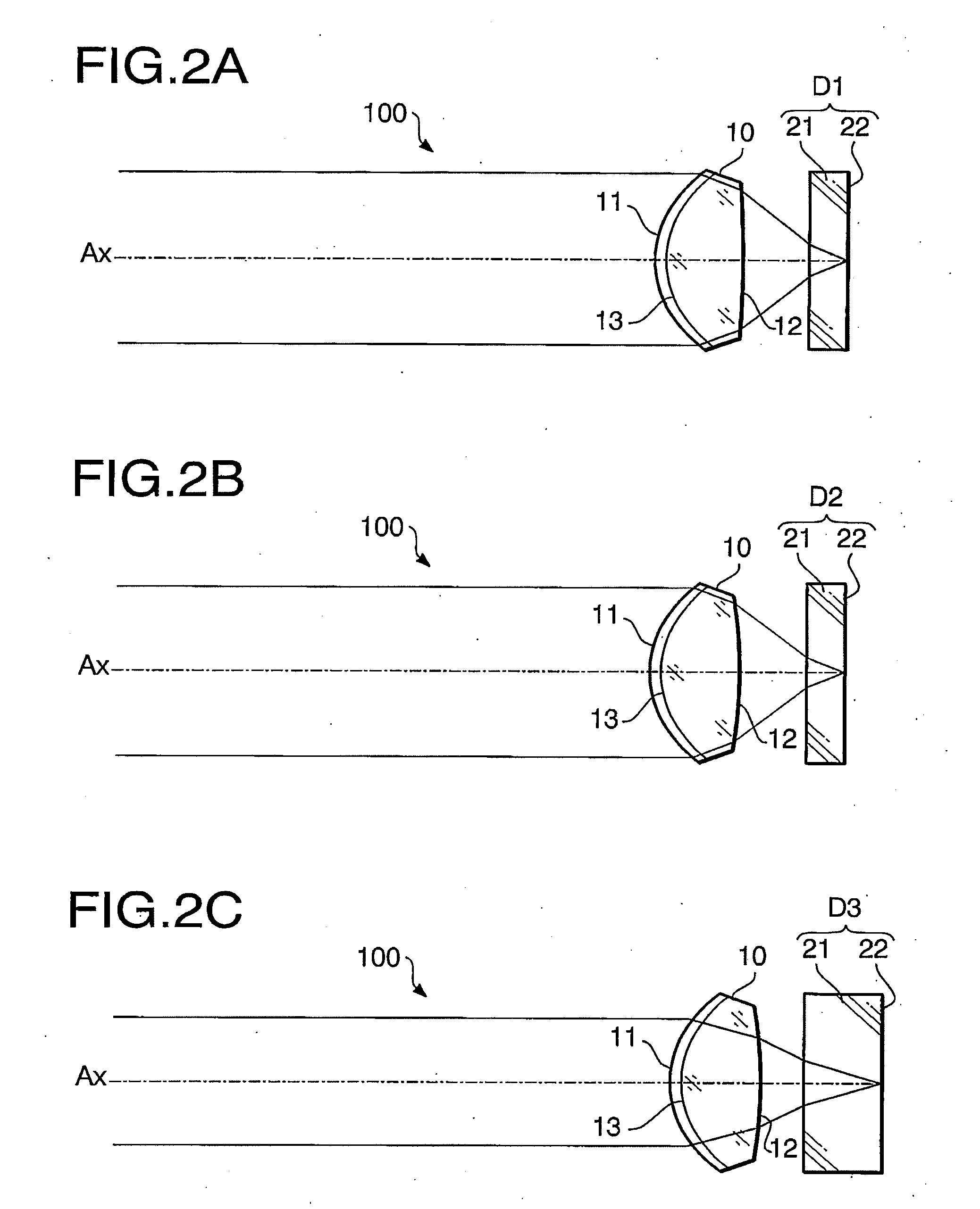
[0070]The overall configuration of the objective lens 10 as a first example is shown in FIG. 3. The cementing surface 13 of the objective lens 10 of the first example is provided with a diffracting structure designed so that the ratio among the diffraction orders of the first through third laser beams maximizing their diffraction efficiency will be 3:2:2 (according to the aforementioned first configuration example). The following Table 1 shows the refractive indexes of the first and second optical members 10A and 10B (forming the objective lens 10 of the first example having such a diffracting structure) for the first through third laser beams.

TABLE 11ST laser beam2nd laser beam3rd laser beamwavelength (nm)405660790refractive index n11.574941.556701.55311refractive index n21.560231.540441.53653

[0071]According to Table 1, the values of the conditions (1), (2) and (5) of the objective lens 10 of the first example are 1.105, 1.127 and 0.015, respectively. Thus, the objective lens 10 of...

second example

[0072]The overall configuration of the objective lens 10 as a second example is also shown in FIG. 3. The cementing surface 13 of the objective lens 10 of the second example is provided with a diffracting structure designed so that the ratio among the diffraction orders of the first through third laser beams maximizing their diffraction efficiency will be 5:3:3 (according to the aforementioned second configuration example). The following Table 2 shows the refractive indexes of the first and second optical members 10A and 10B (forming the objective lens 10 of the second example having such a diffracting structure) for the first through third laser beams.

TABLE 21ST laser beam2nd laser beam3rd laser beamwavelength (nm)405660790refractive index n11.583741.565841.56228refractive index n21.560231.540441.53653

[0073]According to Table 2, the values of the conditions (3), (4) and (5) of the objective lens 10 of the second example are 1.080, 1.095 and 0.024, respectively. Thus, the objective ...

third example

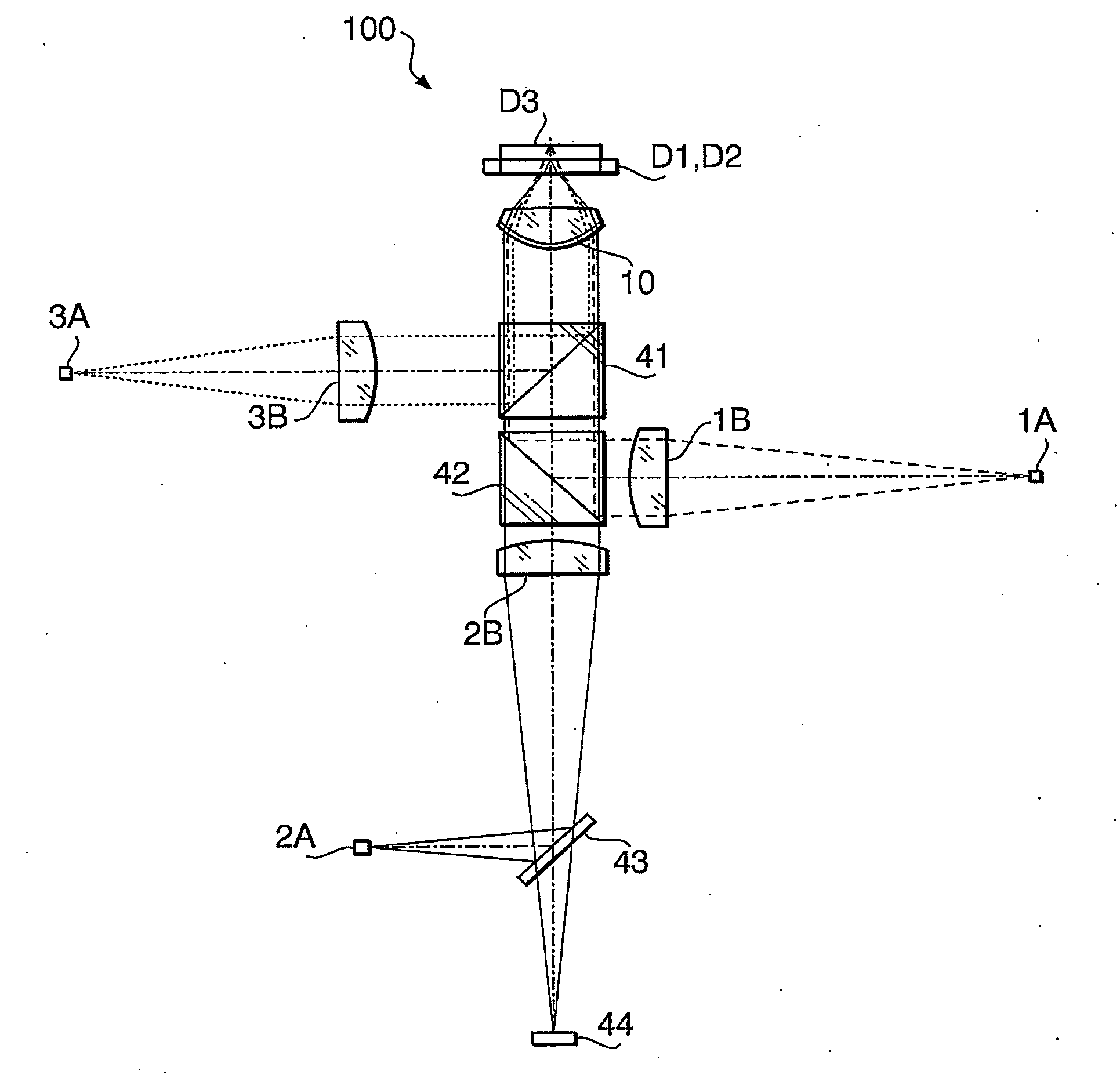
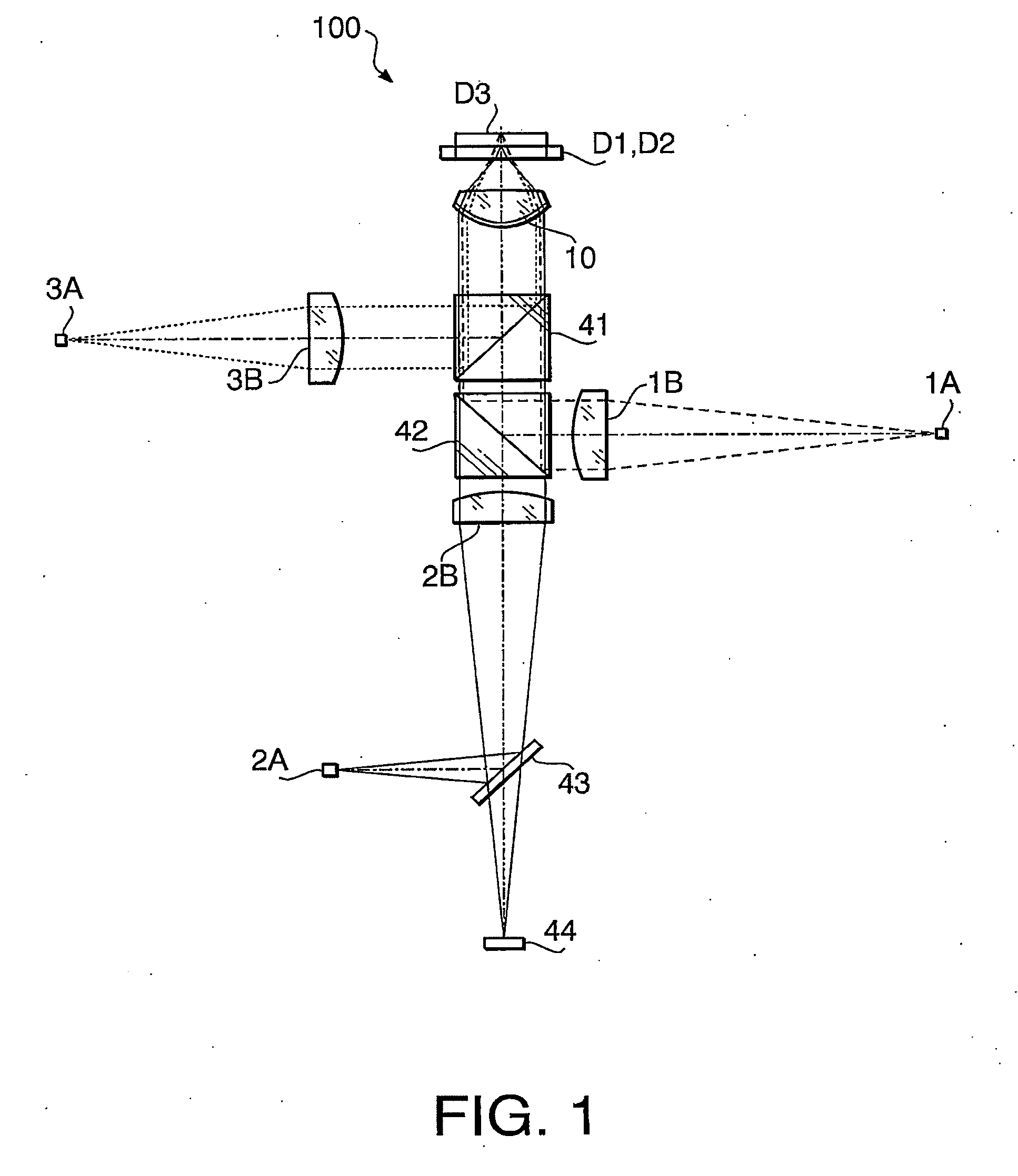
[0074]A third example described below is a specific example of the optical information recording / reproducing device 100 equipped with the objective lens 10 of the embodiment. The overall configuration of the optical information recording / reproducing device 100 of the third example is shown in FIG. 1. The following Table 3 shows concrete specifications of the objective lens 10 of the optical information recording / reproducing device 100 of the third example.

TABLE 31st laser beam2nd laser beam3rd laser beamWavelength (nm)405660790Focal Length (mm)3.003.103.12NA0.650.630.51Magnification M0.0000.0000.000

[0075]As indicated by the “Maginfication M” in Table 3, the laser beam is incident upon the objective lens 10 as a collimated beam in the optical information recording / reproducing device 100 of the third example irrespective of which of the optical discs D1-D3 is used (i.e. irrespective of which of the first through third laser beams is used). The following Tables 4-6 show specific numeri...


PUM

PropertyMeasurementUnit
wavelengthaaaaaaaaaa
densitiesaaaaaaaaaa

Abstract

An objective lens for an optical information recording / reproducing device (executing information reading or writing on first through third optical discs having different data densities and different protective layer thicknesses t1-t3 (t1≦t2≦t3)) by selectively using first through third substantially collimated light beams having first through third wavelengths λ1-λ3 (λ1<λ2<λ3) respectively) includes a first optical member and a second optical member which are cemented together at a cementing surface. At least an area of the cementing surface within an incidence height necessary for securing a numerical aperture NA3 (required for the information read / write on the third optical disc) is provided with a diffracting structure including annular zones. The diffracting structure is formed so that diffraction orders m(λ1), m(λ2) and m(λ3) of the first through third light beams maximizing their diffraction efficiency satisfy m(λ1)>m(λ2)≧m(λ3)≧1.

Description

BACKGROUND OF THE INVENTION[0001]The present invention relates to an objective lens which is installed in a device employing multiple types of light beams having different wavelengths, such as an optical information recording / reproducing device for reading or writing information from / to multiple types of optical discs differing in data density.[0002]There exist various standards of optical discs (CD, DVD, etc.) differing in data density, protective layer thickness, etc. Meanwhile, new-standard optical discs (HD DVD (High-Definition DVD), BD (Blu-ray Disc), etc.), having still higher data density than DVD, are being brought into practical use in recent years to realize still higher information storage capacity. The protective layer thickness of such a new-standard optical disc is substantially equal to or less than that of DVD. In consideration of user convenience with such optical discs according to multiple standards, the optical information recording / reproducing devices (more spec...

Claims


Application Information

Patent Timeline
Patent Type & Authority Applications(United States)
IPC IPC(8): G11B7/00
CPCG02B27/1013G02B27/144G11B2007/0006G11B7/1353G11B7/1374G02B27/145
Inventor KOIZUMI, TOMOKAZUTAKEUCHI, SHUICHIKOREEDA, DAISUKE
Owner ASAHI KOGAKU KOGYO KK
Learn More