Wide-angle imaging optical system and wide-angle imaging apparatus surveillance imaging apparatus vehicle-mounted imaging apparatus and projection apparatus using the wide-angle imaging optical system

a wide-angle imaging and optical system technology, applied in the field of wide-angle imaging optical system and wide-angle imaging apparatus surveillance imaging apparatus, can solve the problems of increasing the weight of the optical system, increasing the size of the apparatus, increasing the cost of the apparatus, etc., and achieves the effects of improving aberration correction, simple structure, and long back focal length

Inactive Publication Date: 2008-08-05
PANASONIC CORP
View PDF13 Cites 33 Cited by
  • Summary
  • Abstract
  • Description
  • Claims
  • Application Information

AI Technical Summary

Benefits of technology

[0011]To solve the above conventional problems, it is an object of the present invention to provide a wide-angle imaging optical system that can produce a panoramic image covering a maximum horizontal angle of view of 360 degrees as well as an image in the vicinity of the axial direction with a simple structure and has a relatively long back focal length, improved aberration correction, and brightness.

Problems solved by technology

However, a wide-angle imaging optical system using, e.g., a fish-eye lens generally requires many lenses.
Therefore, the weight of the optical system is increased, and the apparatus becomes large and expensive.
Moreover, the generation of chromatic aberration or the like is a problem, and actually this wide-angle imaging optical system is only used for taking pictures with special techniques.
Therefore, a transparent material used for the rotating body is thick, and when the transparent material is resin, it is susceptible to temperature changes and takes longer to be molded.
When the transparent material is glass, particularly aspherical glass, considerable cost is involved in polishing the glass.
Consequently, the master lens becomes large and complicated.

Method used


Image

  • Wide-angle imaging optical system and wide-angle imaging apparatus surveillance imaging apparatus vehicle-mounted imaging apparatus and projection apparatus using the wide-angle imaging optical system
  • Wide-angle imaging optical system and wide-angle imaging apparatus surveillance imaging apparatus vehicle-mounted imaging apparatus and projection apparatus using the wide-angle imaging optical system
  • Wide-angle imaging optical system and wide-angle imaging apparatus surveillance imaging apparatus vehicle-mounted imaging apparatus and projection apparatus using the wide-angle imaging optical system

Examples


embodiment 1

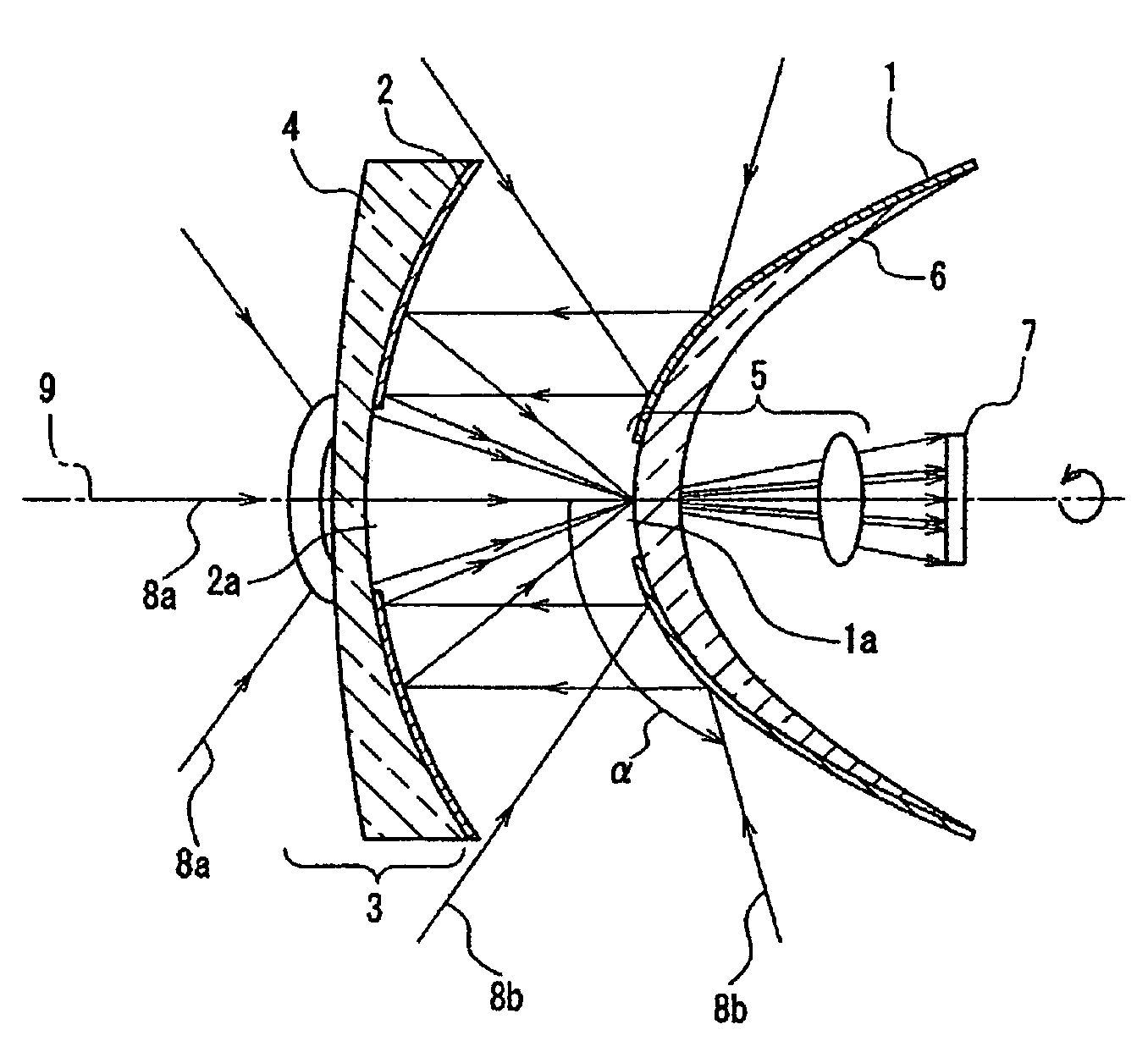
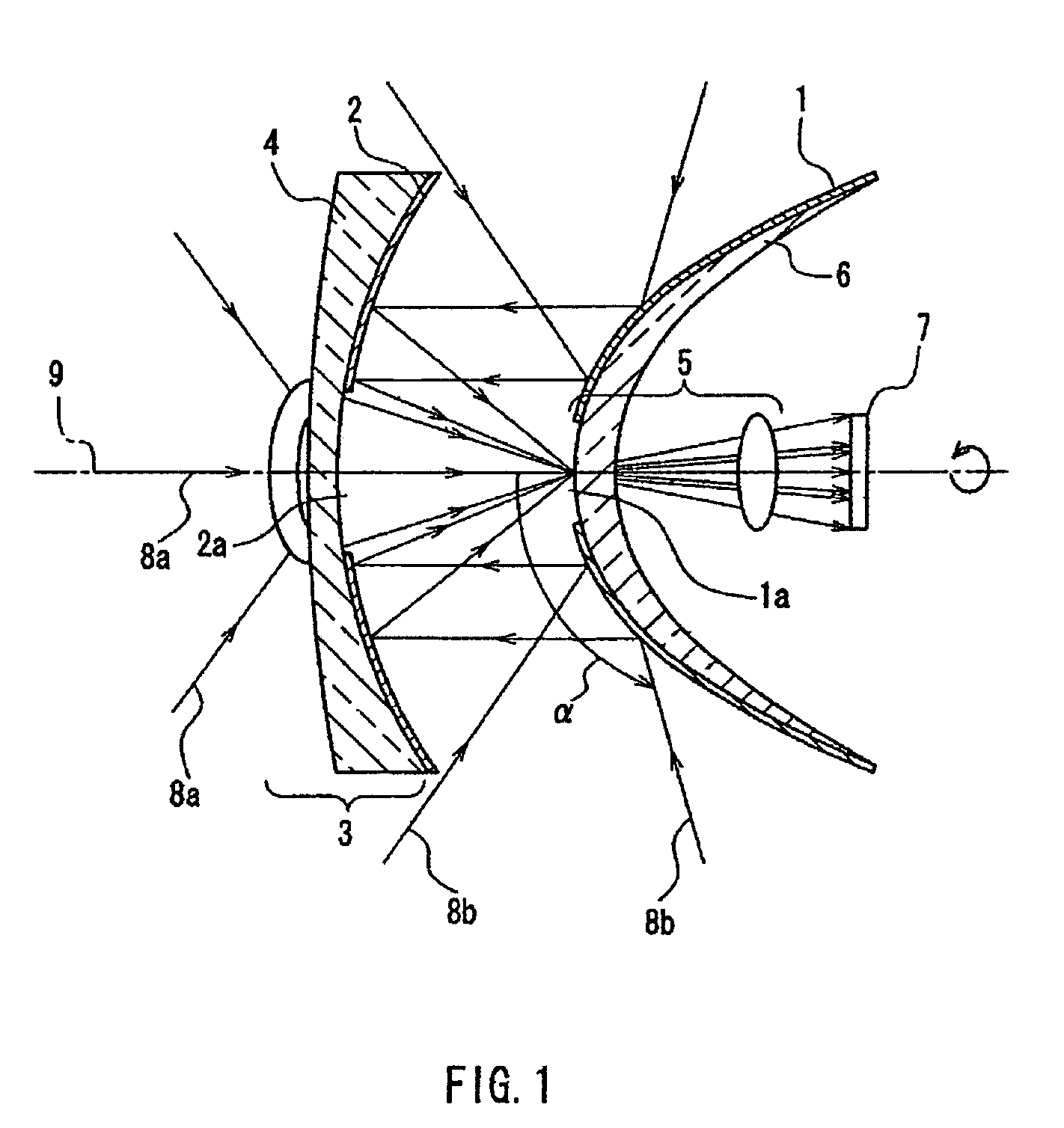
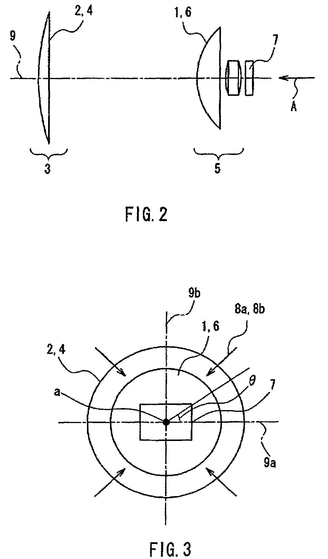
[0122]FIG. 1 is a schematic cross-sectional view showing the basic configuration of a wide-angle imaging apparatus in Embodiment 1, taken along a plane containing a central axis 9. FIG. 2 is a side view of the substantial portion of the apparatus. FIG. 3 is a view in the direction of the arrow A in FIG. 2. FIG. 4 is a perspective view of the substantial portion of the apparatus. The wide-angle imaging apparatus in FIG. 1 includes a refractive optical system 3, a reflective optical system composed of a first reflection surface 1 and a second reflection surface 2, and an image-forming optical system 5. The central axis 9 joins centers of curvature of the first reflection surface 1 and the second reflection surface 2.

[0123]The optical system of the wide-angle imaging apparatus in FIG. 1 includes a first optical system and a second optical system. For the first optical system, the reflective optical system and the image-forming optical system 5 are arranged in the indicated order as see...

embodiment 2

[0135]FIGS. 6 and 7 are schematic cross-sectional views showing the basic configuration of a wide-angle imaging apparatus in Embodiment 2, taken along a plane containing a central axis 9. This embodiment is the same as Embodiment 1 (FIGS. 1 to 5) in basic configuration, but different in that a third reflection surface 61 with a flat surface of reflection is arranged in the optical path between the image-forming optical system 5 and the imaging device 7.

[0136]In FIG. 6, incident light 8a from the outside is refracted by the refractive optical system 3, passes through the light-transmitting portion 2a provided in the second reflection surface 2 and the aperture 1a provided in the first reflection surface 1, then is imaged by the image-forming optical system 5, reflected by the third reflection surface 61 in one direction, and picked up by the imaging device 7. Incident light 8b from the outside is reflected successively by the convex surface of the first reflection surface 1 and the c...

embodiment 3

[0139]FIG. 9 is a schematic cross-sectional view showing the basic configuration of a wide-angle imaging apparatus in Embodiment 3, taken along a plane containing a central axis 9. This embodiment is the same as Embodiment 2 (FIGS. 6 to 8) in basic configuration, but different in that the third reflection surface is curved.

[0140]In FIG. 9, incident light 8a from the outside is refracted by the refractive optical system 3, passes through the light-transmitting portion 2a provided in the second reflection surface 2 and the aperture 1a provided in the first reflection surface 1, then is imaged by the image-forming optical system 5, reflected by a third reflection surface 91 with a curved surface of reflection in one direction, further imaged by the image-forming optical system 5, and picked up by the imaging device 7. Incident light 8b from the outside is reflected successively by the convex surface of the first reflection surface 1 and the concave surface of the second reflection surf...


PUM

PropertyMeasurementUnit
infrared wavelengthaaaaaaaaaa
vertical angleaaaaaaaaaa

Abstract

A wide-angle imaging optical system includes a refractive optical system (3), a reflective optical system, and an image-forming optical system (5). The reflective optical system includes a first reflection surface (1) that directly reflects rays of light from an object, and a second reflection surface (2) that reflects rays of light from the first reflection surface (1). An open portion is provided between the first reflection surface (1) and the second reflection surface (2), and rays of light from the object enter the open portion. A light-transmitting portion (2a) is provided in the second reflection surface (2) and transmits rays of light that have entered the refractive optical system (3). An aperture (1a) is provided in the first reflection surface (1) and allows rays of light from the second reflection surface (2) and the refractive optical system (3) to enter the image-forming optical system (5).

Description

TECHNICAL FIELD[0001]The present invention relates to a wide-angle imaging apparatus that can produce a panoramic image covering an ultra-wide range by using the combination of reflection surfaces and the combination of lenses.BACKGROUND ART[0002]Various research and development have been conducted on a wide-angle imaging apparatus to efficiently produce an image of an object in a large area. One example is the development of a wide-angle camera with a fish-eye lens.[0003]JP 10(1998)-54939 A (REFLECTION TYPE VIEWING ANGLE CONVERTING OPTICAL DEVICE AND OPTICAL SYSTEM USING THE DEVICE) proposes a system that produces an image of a wide visual field by variously changing the shapes of three mirror surfaces arranged opposite to each other. JP 2000-4383 A (MULTIDIRECTIONAL IMAGE TAKING-IN DEVICE) proposes an optical system that produces a counter image inside a normal image by using a shaft of a panoramic image block as a lens.[0004]JP 2001-94839 A (WIDE VISUAL FIELD IMAGE PICKUP DEVICE ...

Claims


Application Information

Patent Timeline
Patent Type & Authority Patents(United States)
IPC IPC(8): G02F1/15G02B13/06G02B17/06G02B17/08G02B27/00
CPCG02B13/06G02B27/0018G02B17/0694G02B17/061H04N23/00
Inventor MATSUKI, DAIZABUROYOSHIKAWA, MOTONOBUYAMAMOTO, YOSHIHARU
Owner PANASONIC CORP
Why Eureka
Try Eureka