Projection optical unit and projection image display apparatus

a projection optical unit and projection image technology, applied in the direction of printers, cameras, instruments, etc., can solve the problems of reducing the thickness of the rear-view mirror, difficult and difficult to achieve such wide-angle imaging, so as to achieve wide-angle imaging and improve the focusing performance. , the effect of improving the focusing performan

Active Publication Date: 2007-01-09
MAXELL HLDG LTD
View PDF10 Cites 9 Cited by
  • Summary
  • Abstract
  • Description
  • Claims
  • Application Information

AI Technical Summary

Benefits of technology

[0012]In this way, to realize more compact dimensions of a rear-projection color image display apparatus, a projection optical unit is required that ensures wider-angle imaging, higher focusing performance, higher magnifications, and longer back-focusing. It is also desirable that even when a panel different in effective screen size and in scheme is used, the amount of development investment should be minimized by partially modifying standard components without redesigning and redeveloping all illumination optics or the projection optical unit.
[0013]The present invention was made in view of the problems and situations mentioned above, and an object of the invention is to provide a technology that allows a more compact set to be obtained.
[0016]Since the first enlarged image obtained by the first projection optical unit is formed closer to the image display element than to the second projection optical unit, F2 (divergence angle of light rays) that is the F-value of the second lens group equals a value obtained by dividing F1, the F-value of the first lens group, by the magnification M1 of the first enlarged image. That is to say, F2=F1 / M1. This makes it possible to increase F2 of the second projection optical unit, thus providing an advantage in implementing very-wide-angle imaging at a field angle exceeding 90 degrees.
[0019](1) Optical path folding means is provided between the above-mentioned second projection optical unit and the field lens group. More specifically, a prism may be used as the technical means for folding an optical path. Use of a fold mirror allows realization of a more compact design with a suppressed increase in cost.

Problems solved by technology

The afocal converter disclosed in Patent document 1 is low in magnification, and thus, wide-angle imaging is difficult to achieve.
Also, in the projection optical unit described in Patent document 2, it is difficult to achieve such wide-angle imaging that allows sufficient reduction in the thickness of a rear-projection color image display apparatus.
There is yet another problem in that since each of the lenses used needs to be independently decentered, the projection optical unit is difficult to manufacture.
Since at least two lenses in the second refractive lens system that has negative power are decentered with a difference in rotational symmetry, there is the manufacturing-related problem in which position accuracy of each lens is difficult to achieve.
Furthermore, in each of the above conventional technologies, design has focused only on the projection optical unit and the optimal design has not been conducted for the entire system that includes illumination optics.
Problems with the projection optical unit used for the conventional color image display apparatus employing a transmission-type liquid-crystal panel as an image display element, include as described above, in addition to the difficulty in achieving wider-angle imaging required for a more compact design of the set, the difficulties in obtaining higher focusing performance to respond to the improvement of the panel in resolution, and in enhancing magnifications to cope with the downsizing of the panel and the color image display apparatus.

Method used


Image

  • Projection optical unit and projection image display apparatus
  • Projection optical unit and projection image display apparatus
  • Projection optical unit and projection image display apparatus

Examples


embodiment 1-1

[Embodiment 1-1]

[0096]Embodiment 1 of a first projection optical unit is described using FIGS. 3 to 12 and Table 1.

[0097]

TABLE 1Radius ofIntersurfaceSurface No.CurvatureDistanceGlass MaterialObject surface∞6.5281∞31.342BSC7_HOYA2∞7.333190.86.1TAF3_HOYA4−55.50.2567.0593.29TAF3_HOYA6382.40.2734.83.61TAF3_HOYA860.1729.79−268.571EFD8_HOYA1042.278.311−439.450.8EFD8_HOYA1217.9763.02FCD1_HOYA13−400.214(Aperture stop21.1153.85BACD18_HOYAsurface)1584.814.141650.6166.92EFD4_HOYA1725.9439.3918−11.0081.8FCD1_HOYA19605.747.8620−72.614.58TAF3_HOYA21−28.10.22265.3114.71TAF3_HOYA23264.9234.8224−31.655.11PMMA25−31.11351st enlarged∞0image surface

[0098]

Surface No.KABCDE2402.6583E−05−7.3374E−081.4933E−10−1.3814E−135.4234E−172503.7074E−05−1.1429E−072.2442E−10−2.0717E−138.0805E−17

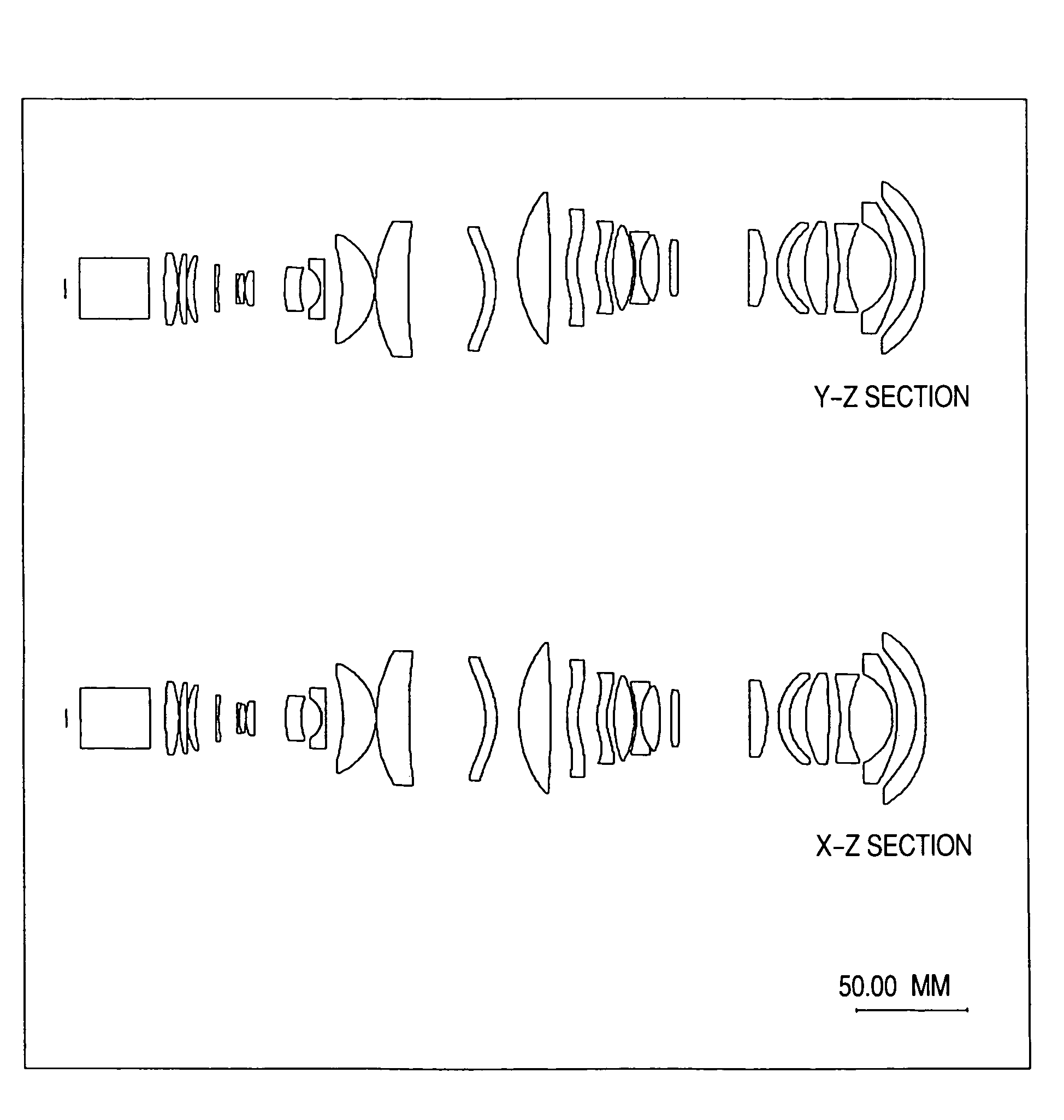
[0099]FIG. 3 is a configuration diagram and spot diagram of a first projection optical unit. This figure indicates the way the luminous flux irradiated from an image display element in a telecentric state converges telecentrical...

embodiment 1-2

[Embodiment 1-2]

[0106]Embodiment 2 of a first projection optical unit is described below using FIGS. 13 to 22 and Table 2.

[0107]

TABLE 2Radius ofIntersurfaceSurface No.CurvatureDistanceGlass MaterialObject Surface∞6.528(Panel surface)1∞31.342BSC7_HOYA2∞7.333176.22376.1TAF3_HOYA4−46.360.2536.33453.99TAF3_HOYA6106.50.2758.8952.82TAF3_HOYA865.4366.879−79.82731EFD8_HOYA10297.89.8811−102.380.8EFD8_HOYA1215.96363.02FCD1_HOYA13−32.730.214(Aperture stop18.65023.85BACD18_HOYAsurface)1531.106617.971623.917.5EFD4_HOYA1719.57.5418−11.253783211.8FCD1_HOYA19217.6311.3520−7513.47TAF3_HOYA21−30.68140.22257.047311.85TAF3_HOYA23305.564222.9524−37.40723.5PMMA25−48.90257.8761st enlarged∞0image surface(Image surface)

[0108]

Surface No.KABCDE2403.4526E−05−3.6247E−083.3065E−11−1.4755E−143.6803E−182503.5425E−05−5.1937E−088.6015E−11−9.3416E−145.0304E−17

[0109]FIG. 13 is a configuration diagram and spot diagram of Embodiment 2 of a first projection optical unit according to the present invention. This figure ind...

embodiment 1-3

[Embodiment 1-3]

[0116]Embodiment 3 of a first projection optical unit is described below using FIGS. 23 to 32 and Table 3.

[0117]

TABLE 3Radius ofIntersurfaceSurface No.CurvatureDistanceGlass MaterialObject surface∞6.52801∞31.342BSC7_HOYA2∞7.333127.70526.1TAF3_HOYA4−49.55080.2534.27474.1764TAF3_HOYA6104.15700.2731.62375.7931TAF3_HOYA834.67215.16519741.76371.8EFD8_HOYA1032.17165.857211−33.54330.5618EFD8_HOYA1215.46282.7796FCD1_HOYA13−27.31830.214(Aperture stop21.14043.85BACD18_HOYAsurface)15302.988916.00961628.35316.6145EFD4_HOYA1722.60326.938418−11.36891.8FCD1_HOYA19212.006510.591120−89.016312.8067TAF3_HOYA21−31.24390.22259.115510.4768TAF3_HOYA23256.477432.959024−38.03083.5PMMA25−35.15106.22081st enlarged∞0image surface(Image surface)

[0118]

Surface No.KABCDE2402.9332E−05−3.1299E−083.7631E−11−2.2287E−144.7490E−182503.6927E−05−4.4805E−085.1104E−11−1.8533E−14−1.4722E−18  

[0119]FIG. 23 is a configuration diagram and spot diagram of Embodiment 3 of a first projection optical unit according ...


PUM

PropertyMeasurementUnit
field angleaaaaaaaaaa
cone angleaaaaaaaaaa

Abstract

A projection optical unit has two lens groups. A first projection optical unit disposed closest to an image display element, temporarily forms a first enlarged image (magnification: M1) at the image display element side, rather than at a second projection optical unit. The first enlarged image is subsequently projected in an enlarged form (magnification: M2, wherein M2>M1) onto a screen via the second projection optical unit. A field lens group having positive refractive power is disposed between the first projection optical unit and the second projection optical unit. Consequently, the relationship between F2, which is the F-value of the second projection optical unit, and F1, which is the F-value of the first projection optical unit, becomes F2=F1 / M1, whereby it is possible to realize very-wide-angle imaging at a field angle exceeding 90 degrees.

Description

CLAIM OF PRIORITY[0001]The present application claims priority from Japanese application serial no. JP2003-398395, filed on Nov. 28, 2003, the content of which is hereby incorporated by reference into this application.BACKGROUND OF THE INVENTION[0002]The present invention relates to a projection image display apparatus that displays images by projecting them onto the front of a screen or from the rear of the screen. The invention also relates to a projection optical unit used for such a display apparatus.[0003]An image display apparatus that uses a projection optical unit to provide an enlarged on-screen projection of the images displayed by an image display element is required to obtain large enough an enlarged image on the screen, while at the same time, shortening the projection distance. A projection optical unit is known that is adapted to implement the above by projecting an image in enlarged form from an oblique direction with respect to a screen, as described in, for example...

Claims


Application Information

Patent Timeline
Patent Type & Authority Patents(United States)
IPC IPC(8): G03B21/14G02B15/14G02B23/24G02B3/10G02B9/06G02B13/24G02B9/12G02B13/18G02B13/22G02B27/18G02F1/13G02F1/1335G03B21/00
CPCG03B21/14G02B13/22G03B21/142
Inventor YATSU, MASAHIKOHIRATA, KOJIIKEDA, HIDEHIRO
Owner MAXELL HLDG LTD
Why Eureka
Try Eureka