

Zoom lens and image projection apparatus having the same
a technology of zoom lens and image projection apparatus, which is applied in the field of zoom lens, can solve the problems that the above-described conventional zoom lens cannot respond to a growing desire, and achieve the effects of wide angle of view, easy projecting high-quality images, and long back focal distan
- Summary
- Abstract
- Description
- Claims
- Application Information
AI Technical Summary
Benefits of technology
Problems solved by technology
Method used
Image

Examples
first exemplary embodiment
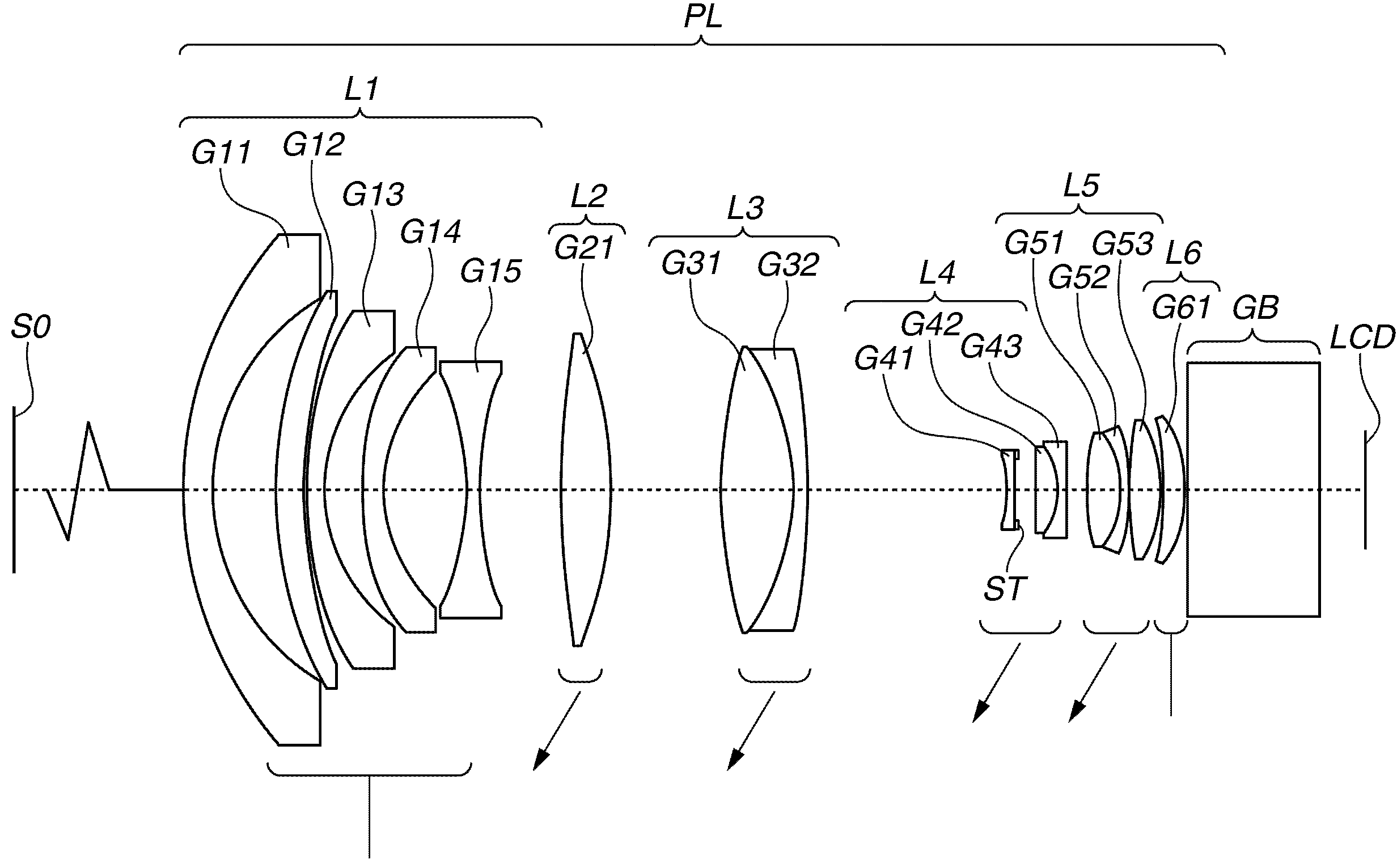
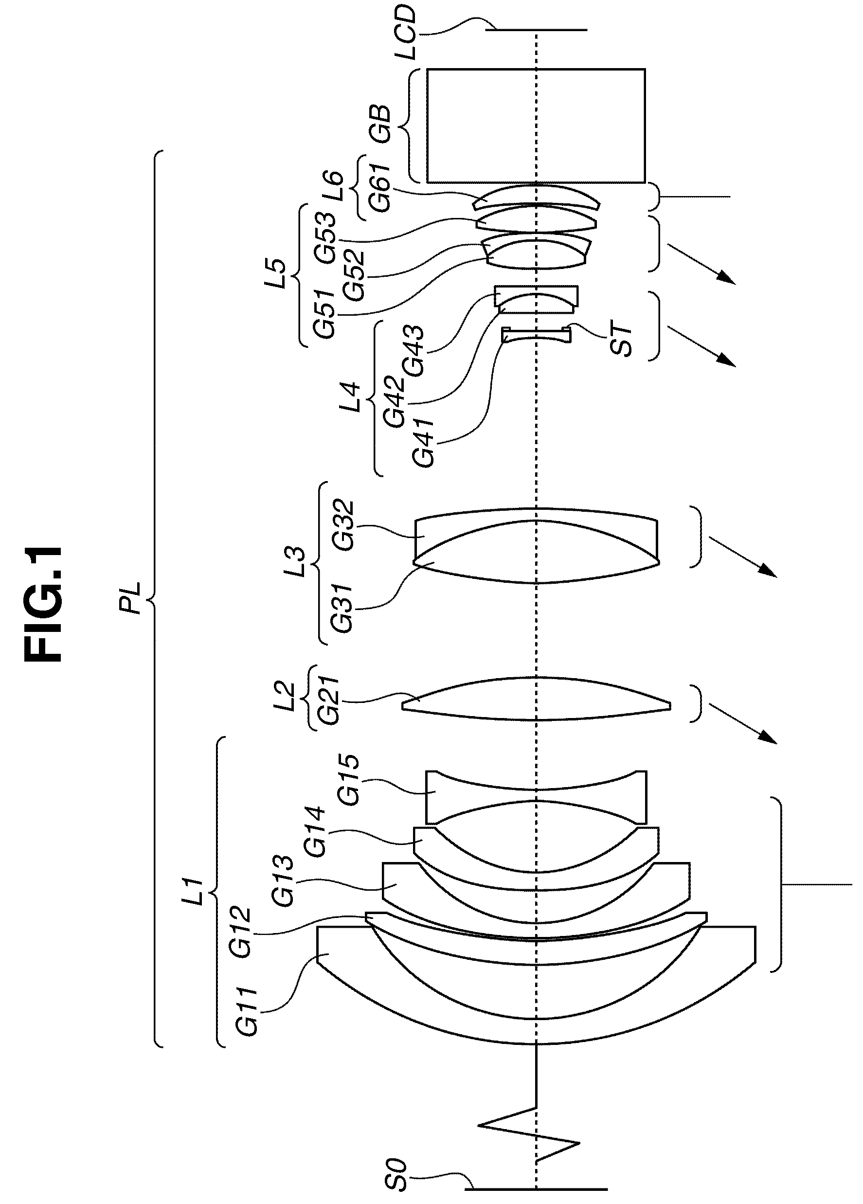
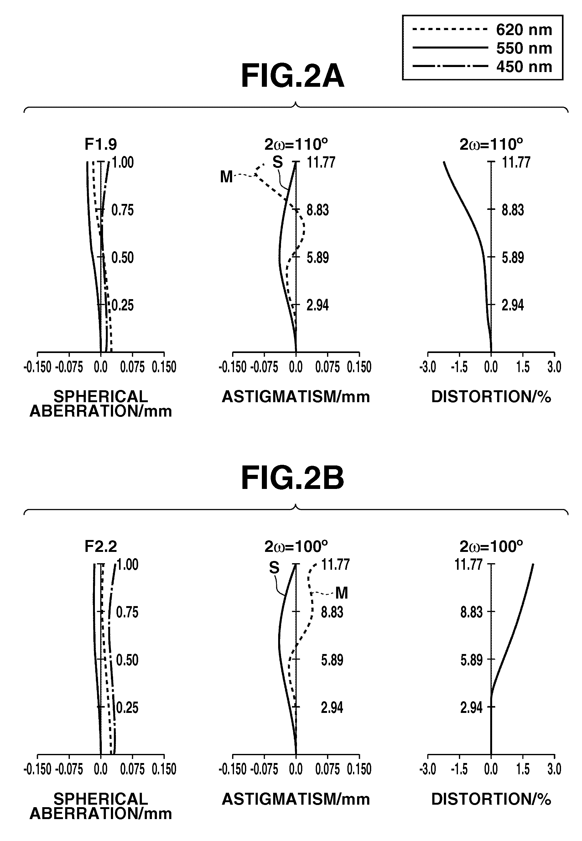
[0086]A first exemplary embodiment of the present invention is described below. FIG. 1 illustrates components of the zoom lens according to the first exemplary embodiment. Table 1 shows the lens data for the zoom lens according to the first exemplary embodiment. FIG. 2A illustrates various aberrations occurring in the zoom lens at the wide-angle end according to the first exemplary embodiment. FIG. 2B illustrates various aberrations occurring in the zoom lens at the telephoto end according to the first exemplary embodiment. Referring to FIG. 1, the zoom lens comprises (consists of or includes) a first lens unit L1 having a negative refractive power (optical power), a second lens unit L2 having a positive refractive power (optical power), a third lens unit L3 having a positive refractive power (optical power), a fourth lens unit L4 having a negative refractive power (optical power), a fifth lens unit L5 having a positive refractive power (optical power), and a sixth lens unit L6 havi...
second exemplary embodiment
[0098]A second exemplary embodiment of the present invention is described below. FIG. 3 illustrates components of the zoom lens according to the second exemplary embodiment. Table 2 shows the lens data for the zoom lens according to the second exemplary embodiment. FIG. 4A illustrates various aberrations occurring in the zoom lens at the wide-angle end according to the second exemplary embodiment. FIG. 4B illustrates various aberrations occurring in the zoom lens at the telephoto end according to the second exemplary embodiment. Referring to FIG. 3, the zoom lens comprises (consists of or includes) a first lens unit L1 having a negative refractive power (optical power), a second lens unit L2 having a positive refractive power (optical power), a third lens unit L3 having a positive refractive power (optical power), a fourth lens unit L4 having a negative refractive power (optical power), a fifth lens unit L5 having a positive refractive power (optical power), and a sixth lens unit L6...
third exemplary embodiment
[0107]A third exemplary embodiment of the present invention is described below. FIG. 5 illustrates components of the zoom lens according to the third exemplary embodiment. Table 3 shows the lens data for the zoom lens according to the third exemplary embodiment. FIG. 6A illustrates various aberrations occurring in the zoom lens at the wide-angle end according to the third exemplary embodiment. FIG. 6B illustrates various aberrations occurring in the zoom lens at the telephoto end according to the third exemplary embodiment. Referring to FIG. 5, the zoom lens comprises (consists of or includes) a first lens unit L1 having a negative refractive power (optical power), a second lens unit L2 having a positive refractive power (optical power), a third lens unit L3 having a positive refractive power (optical power), a fourth lens unit L4 having a negative refractive power (optical power), and a fifth lens unit L5 having a positive refractive power (optical power). “ST” denotes an aperture ...
PUM
 Abstract
Description
Claims
Application Information