Objective lens for endoscope

a technology of objective lens and endoscope, which is applied in the field of objective lens, can solve the problems of difficult to obtain a sufficiently long back focal length, difficult to correct for the lateral color, and the length of the endoscope objective lens tends to decreas

Inactive Publication Date: 2009-03-10
FUJI PHOTO OPTICAL CO LTD
View PDF2 Cites 9 Cited by
  • Summary
  • Abstract
  • Description
  • Claims
  • Application Information

AI Technical Summary

Benefits of technology

[0006]An object of an illustrative, non-limiting embodiment of the invention is to provide an objective lens which can correct for the lateral color satisfactorily while the back focal length is made longer.
[0009]It is preferable that the objective lens satisfies formula (2):v−<22wherein v− represents an Abbe number of the negative lens of the cemented lens. This makes it even easier to correct for the lateral color.

Problems solved by technology

However, to meet the wide angle requirement, the focal lengths of endoscope objective lenses tend to decrease even for the same image size, which makes it difficult to obtain a sufficiently long back focal length.
However, in lens systems having a long back focal length, the optical member is not disposed close to the image forming surface and hence it is not easy to correct for the lateral color.

Method used


Image

  • Objective lens for endoscope
  • Objective lens for endoscope
  • Objective lens for endoscope

Examples


examples

[0042]Next, specific examples of the endoscope objective lens according to the embodiment will be described. Examples 1-4 will be described together below.

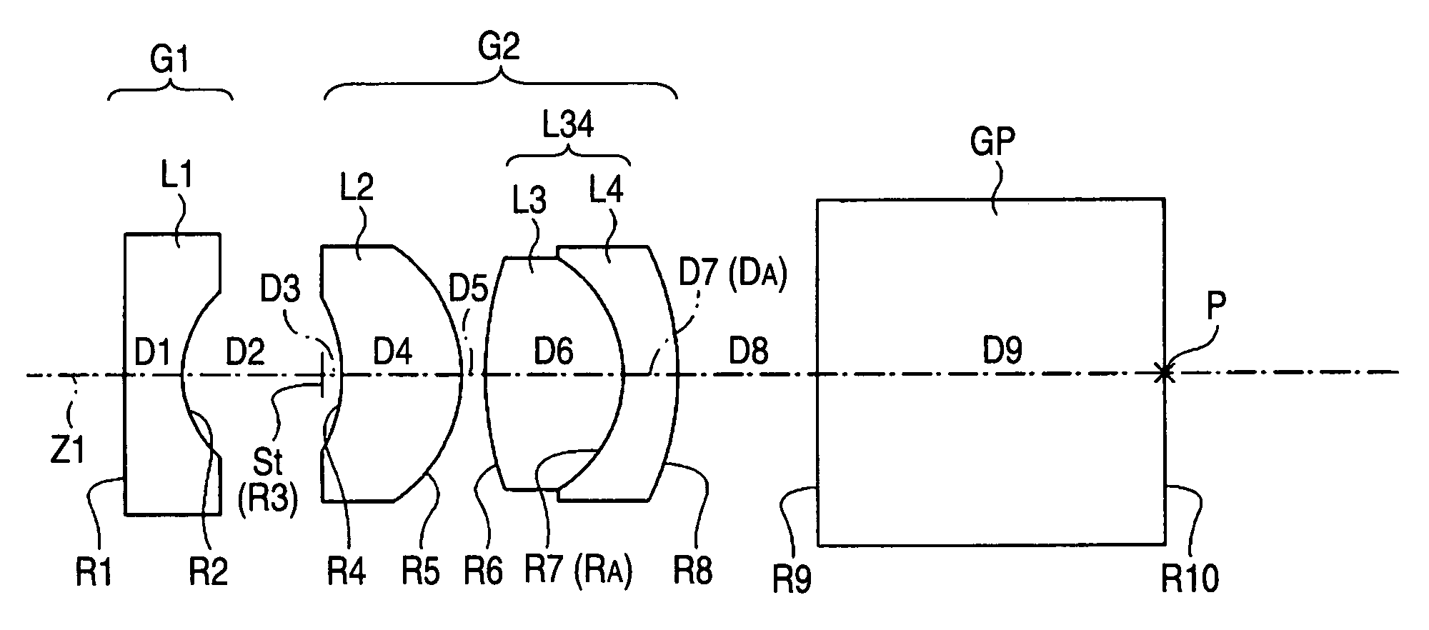
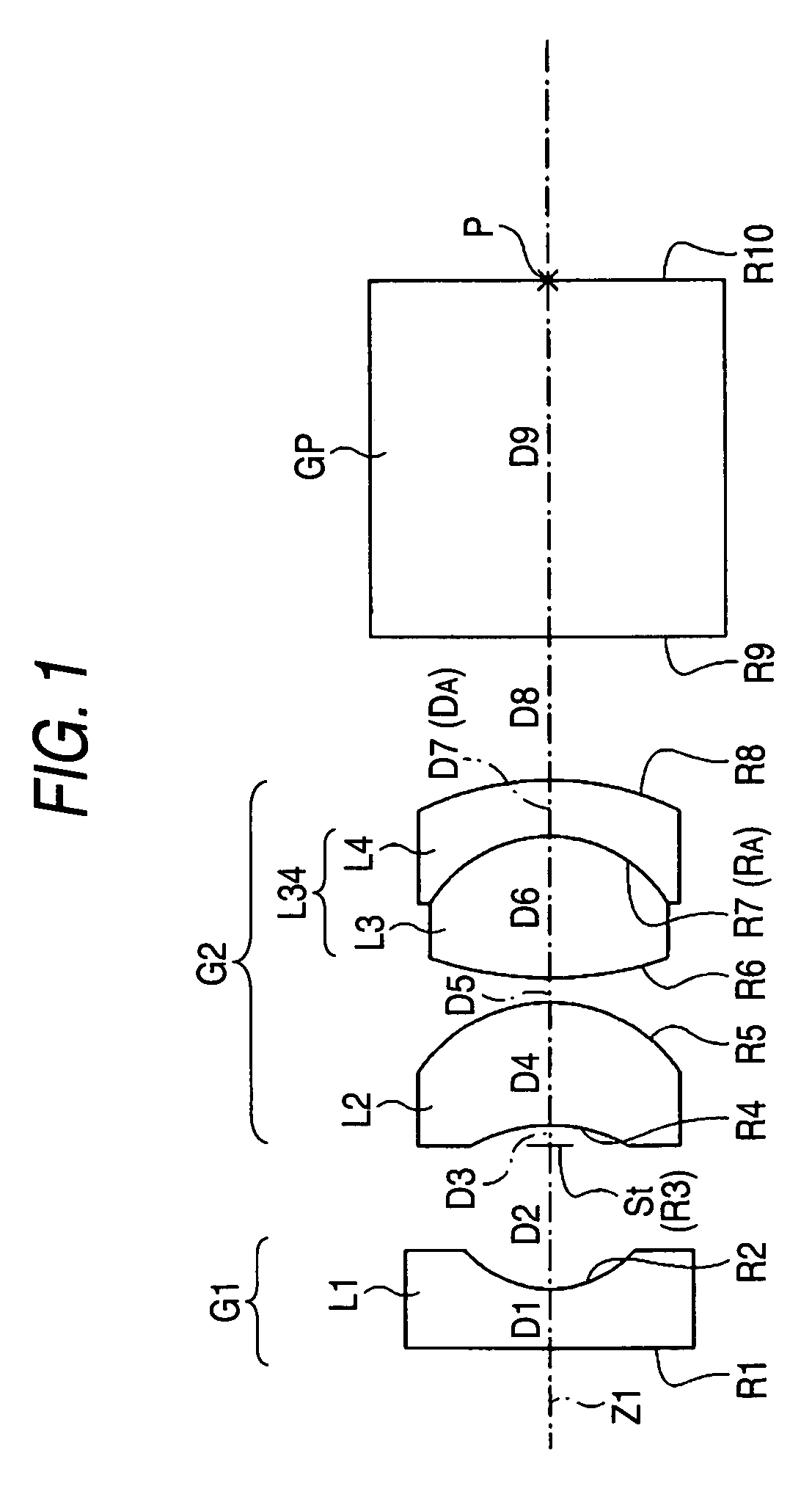
[0043]FIG. 5 shows lens data of the endoscope objective lens according to Example 1. The basic lens configuration of the endoscope objective lens according to Example 1 has already been described above with reference to FIG. 1. In the column “surface Si” of the lens data shown in FIG. 5, symbol Si denotes the ith surface (i=1 to 10) as numbered from the object side to the image side, the object-side end element surface being denoted by S1. In the column “radius Ri of curvature,” the value (mm) of the radius of curvature of the ith surface as numbered from the object side is shown (symbol Ri is the same as shown in FIG. 1). In the column “surface interval Di,” the value (mm) of the surface interval on the optical axis Z1 between the ith surface Si and the (i+1)th surface Si+1 is shown. In the column “refractive index ndj,” the valu...


PUM


Abstract

An endoscope objective lens is provided and has a front-group divergent lens system, an aperture stop, and a rear-group convergent lens system in this order from the object side. The back focal length Bf of the whole system is longer than 2.5 times the combined focal length f of the whole system. The rear-group convergent lens system includes a cemented lens. The endoscope objective lens satisfies the specific formula.

Description

BACKGROUND OF THE INVENTION[0001]1. Field of the Invention[0002]The present invention relates to an objective lens provided in the tip portion of an endoscope. More particularly, the invention relates to an endoscope objective lens capable of being applied to an optical system in which the back focal length is long enough to allow an optical path-changing prism to be disposed on the image side.[0003]2. Description of Related Art[0004]Endoscopes are known in which a solid-state imaging device such as a CCD (charge-coupled device) is provided in the tip portion so as to be parallel with the longitudinal direction. FIG. 17 outlines an objective optical system of such an endoscope. As shown in FIG. 17, a solid-state imaging device 200 is disposed in the tip portion of the endoscope so as to be parallel with the axial direction (longitudinal direction) Z. An optical path-changing prism 102 is inserted between an objective lens 100 and the solid-state imaging device 200 via a cover glass ...

Claims


Application Information

Patent Timeline
Patent Type & Authority Patents(United States)
IPC IPC(8): G02B9/04G02B21/02G02B23/24
CPCG02B9/12G02B23/243
Inventor MIYANO, HITOSHI
Owner FUJI PHOTO OPTICAL CO LTD
Why Eureka
Try Eureka