Wide-angle lens system

a wide-angle lens and lens system technology, applied in the field of wide-angle lens systems, can solve the problems of difficult to increase the size of imaging devices, and achieve the effect of prolonging the back focal distan

Active Publication Date: 2005-10-27
RICOH IMAGING COMPANY
View PDF5 Cites 8 Cited by
  • Summary
  • Abstract
  • Description
  • Claims
  • Application Information

AI Technical Summary

Benefits of technology

[0008] The present invention provides a wide-angle lens system which attains a half angle-of-view of approximately 45° or more, and also attains a longer back focal distance.

Problems solved by technology

A digital SLR camera has usually employed an imaging device whose picture size is smaller than the picture size of a SLR camera with a silver-halide film (hereinafter, an SLR camera), since it has been difficult to increase the size of an imaging device.
Therefore the back focal distance equivalent to that of a SLR camera is structurally required, and a wider angle-of-view becomes inevitably necessary to the extent that a bundle of light rays carrying an object image does not fit the picture size for the imaging device.

Method used


Image

  • Wide-angle lens system
  • Wide-angle lens system
  • Wide-angle lens system

Examples


embodiment 1

[Embodiment 1]

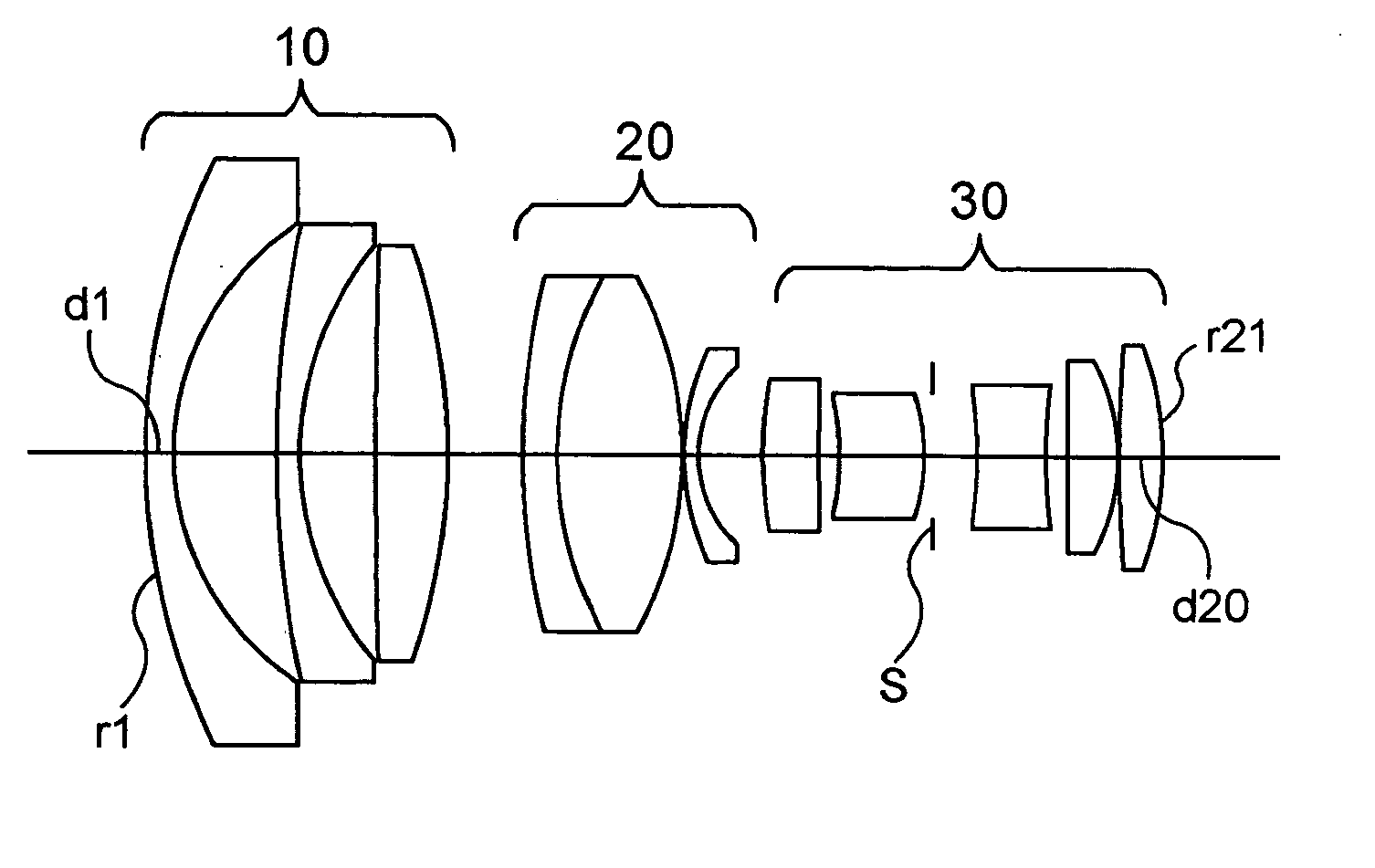
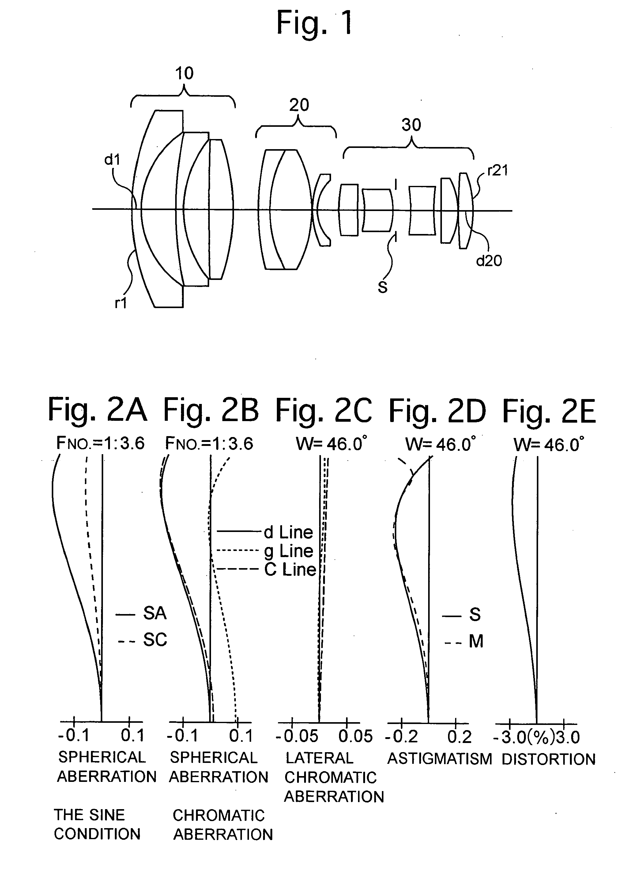
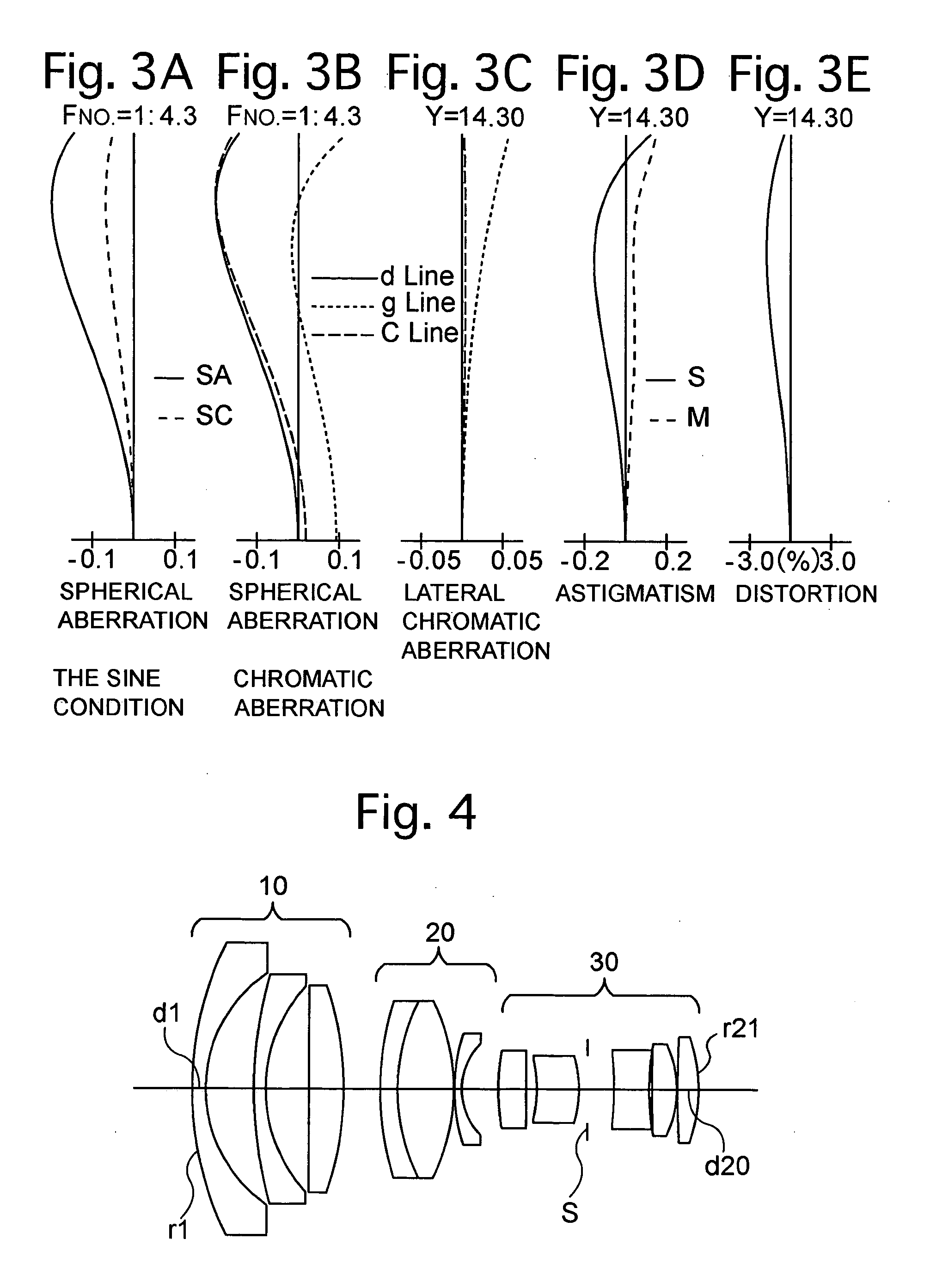
[0074]FIG. 1 is the lens arrangement of the wide-angle lens system according to the first embodiment of the present invention. FIGS. 2A through 2E show aberrations occurred in the lens arrangement of FIG. 1 when an object at infinity is in an in-focus state. FIGS. 3A through 3E show aberrations occurred in the lens arrangement of FIG. 1 when an object at the shortest photographic distance is in an in-focus state. Table 1 shows the numerical data of the first embodiment.

[0075] The negative first lens group 10 includes the two negative meniscus lens elements each having the convex surface facing toward the object, and the positive lens element, in this order from the object.

[0076] The negative second lens group 20 includes the cemented lens elements and the negative meniscus lens element having the convex surface facing toward the object, in this order from the object.

[0077] The positive third lens group 30 includes the positive biconvex lens element, the positive men...

embodiment 2

[Embodiment 2]

[0080]FIG. 4 is the lens arrangement of the wide-angle lens system according to the second embodiment of the present invention. FIGS. 5A through 5E show aberrations occurred in the lens arrangement of FIG. 4 when an object at infinity is in an in-focus state. FIGS. 6A through 6E show aberrations occurred in the lens arrangement of FIG. 4 when an object at the shortest photographic distance is in an in-focus state.

[0081] The basic lens arrangement of the second embodiment is the same as that of the first embodiment.

[0082] Table 2 shows the numerical data of the second embodiment. The diaphragm S is provided 1.2 behind surface No. 15.

TABLE 2FNO. = 1: 3.6-3.6f = 14.41-14.78m = 0.000-−0.136fB = 36.62-38.84Surf.No.rdNdν148.3461.901.7725049.6220.2836.86359.9451.701.8061040.9422.2356.115∞4.931.8051825.46−47.0135.18-2.96743.1042.501.7130053.9828.3888.061.5163364.19−28.3880.111026.6841.001.8040046.6119.4155.211232.8764.001.8051825.413−1071.8451.5214−19.8786.001.4874970.215−...

embodiment 3

[Embodiment 3]

[0083]FIG. 7 is the lens arrangement of the wide-angle lens system according to the third embodiment of the present invention. FIGS. 8A through 8E show aberrations occurred in the lens arrangement of FIG. 7 when an object at infinity is in an in-focus state. FIGS. 9A through 9E show aberrations occurred in the lens arrangement of FIG. 7 when an object at the shortest photographic distance is in an in-focus state.

[0084] The basic lens arrangement of the third embodiment is the same as that of the first embodiment.

[0085] Table 3 shows the numerical data of the third embodiment. The diaphragm S is provided 0.6 behind surface No. 15.

TABLE 3FNO. = 1: 2.9-3.0f = 14.40-14.66m = 0.000-−0.132fB = 36.15-38.17Surf. No.rdNdν148.4862.201.7725049.6222.7018.05369.0961.701.7725049.6427.8625.655239.4145.301.7847026.36−64.5607.99-5.96755.6411.441.7130053.9822.6976.641.5163364.19−33.2130.111025.9201.001.8040046.6119.0652.571229.8624.001.7847026.313−121.2201.6214−14.4906.001.4874970.2...


PUM


Abstract

A wide-angle lens system includes a negative first lens group, a negative second lens group, and a positive third lens group. The negative first lens group includes at least two negative meniscus lens elements each having the convex surface facing toward the object, and a positive lens element provided on the image-side of the two negative meniscus lens elements. The negative second lens group includes cemented lens elements and a negative meniscus lens element having the convex surface facing toward the object. The wide-angle lens system satisfies the following conditions:
f2-3/f>1.6  (1)
f3/f>1.5  (2)
(f2-3/f)/(f3/f)>1.0  (3)
wherein
    • f2-3 designates the combined focal length of the negative second lens group and the positive third lens group; f designates the focal length of the entire wide-angle lens system; and
    • f3 designates the focal length of the positive third lens group.

Description

BACKGROUND OF THE INVENTION [0001] 1. Field of the Invention [0002] The present invention relates to a wide-angle lens system used in a single-lens-reflex (SLR) type electronic digital still camera (hereinafter, a digital SLR camera). [0003] 2. Description of the Prior Art [0004] A digital SLR camera has usually employed an imaging device whose picture size is smaller than the picture size of a SLR camera with a silver-halide film (hereinafter, an SLR camera), since it has been difficult to increase the size of an imaging device. [0005] On the other hand, the lens mount of a digital SLR camera is often made common to that of an SLR camera, such as ones disclosed in Japanese Unexamined Patent Publication (JUPP) No. 6-160706 and JUPP No. 2003-29141. Due to this arrangement, many types of photographic lenses for SLR cameras, which have already been available on the market, can be utilized as an exchangeable photographic lens for digital SLR cameras. [0006] However, in the case where a ...

Claims


Application Information

Patent Timeline
Patent Type & Authority Applications(United States)
IPC IPC(8): G02B13/04G02B9/12G02B13/06G02B15/14G02B15/177
CPCG02B15/177G02B13/06
Inventor HIRAKAWA, JUN
Owner RICOH IMAGING COMPANY
Why Eureka
Try Eureka