Ultraviolet imaging system

an imaging system and ultraviolet light technology, applied in the field of ultraviolet light imaging systems, can solve the problems of insufficient distortion correction, inconvenient converging lens system, insufficient wide-angle lens system, etc., and achieve the effect of longer back focal distan

Inactive Publication Date: 2006-06-06
RICOH IMAGING COMPANY
View PDF10 Cites 10 Cited by
  • Summary
  • Abstract
  • Description
  • Claims
  • Application Information

AI Technical Summary

Benefits of technology

[0008]Furthermore, an ultraviolet imaging system of the present invention also achieves a longer back focal distance.

Problems solved by technology

The above-mentioned wide-angle lens system can attain a desirable imaging quality in a typical photographing operation; however, the correcting of distortion is not sufficiently made therein.
Accordingly, a wide-angle lens system is not appropriate for photography in which a distorted image should be eliminated.
Accordingly, a converging lens system is not suitable for an imaging system (photographing system) to be mainly used to photograph an object at a closer distance.

Method used


Image

  • Ultraviolet imaging system
  • Ultraviolet imaging system
  • Ultraviolet imaging system

Examples


embodiment 1

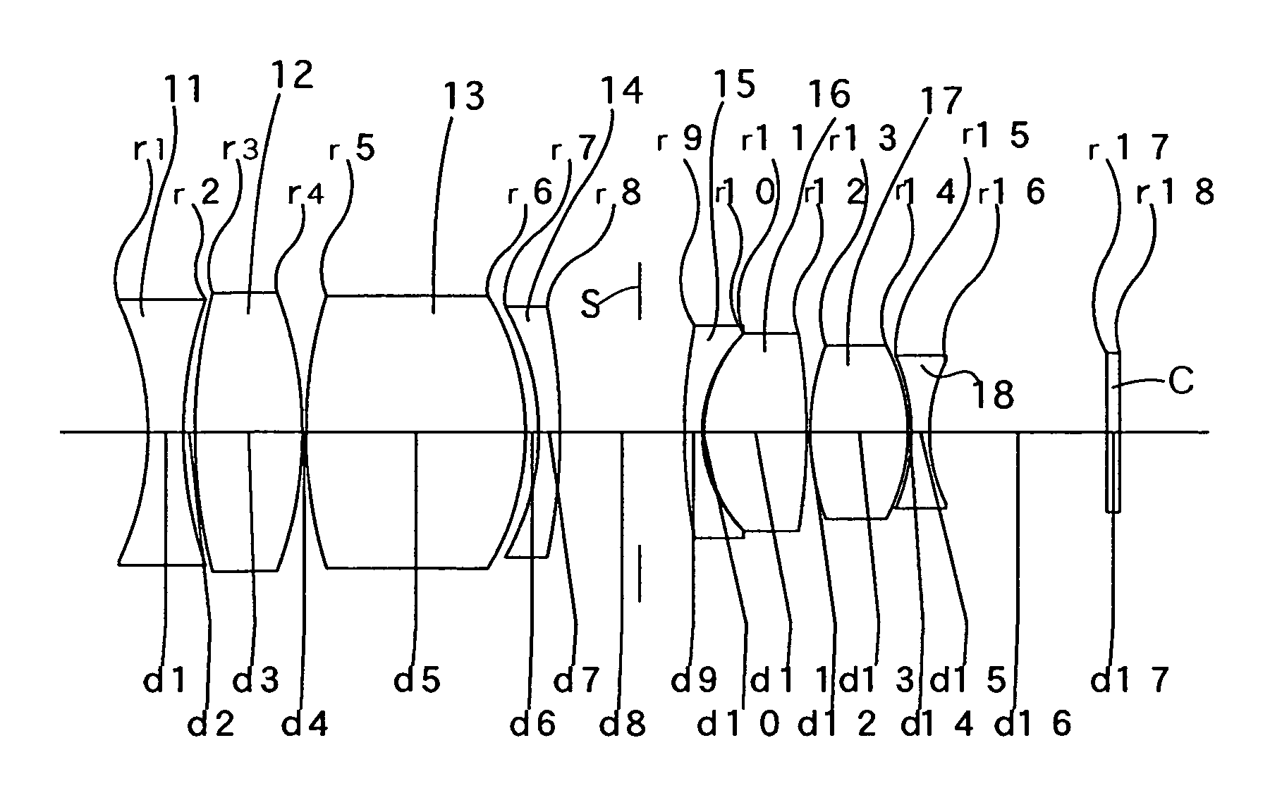
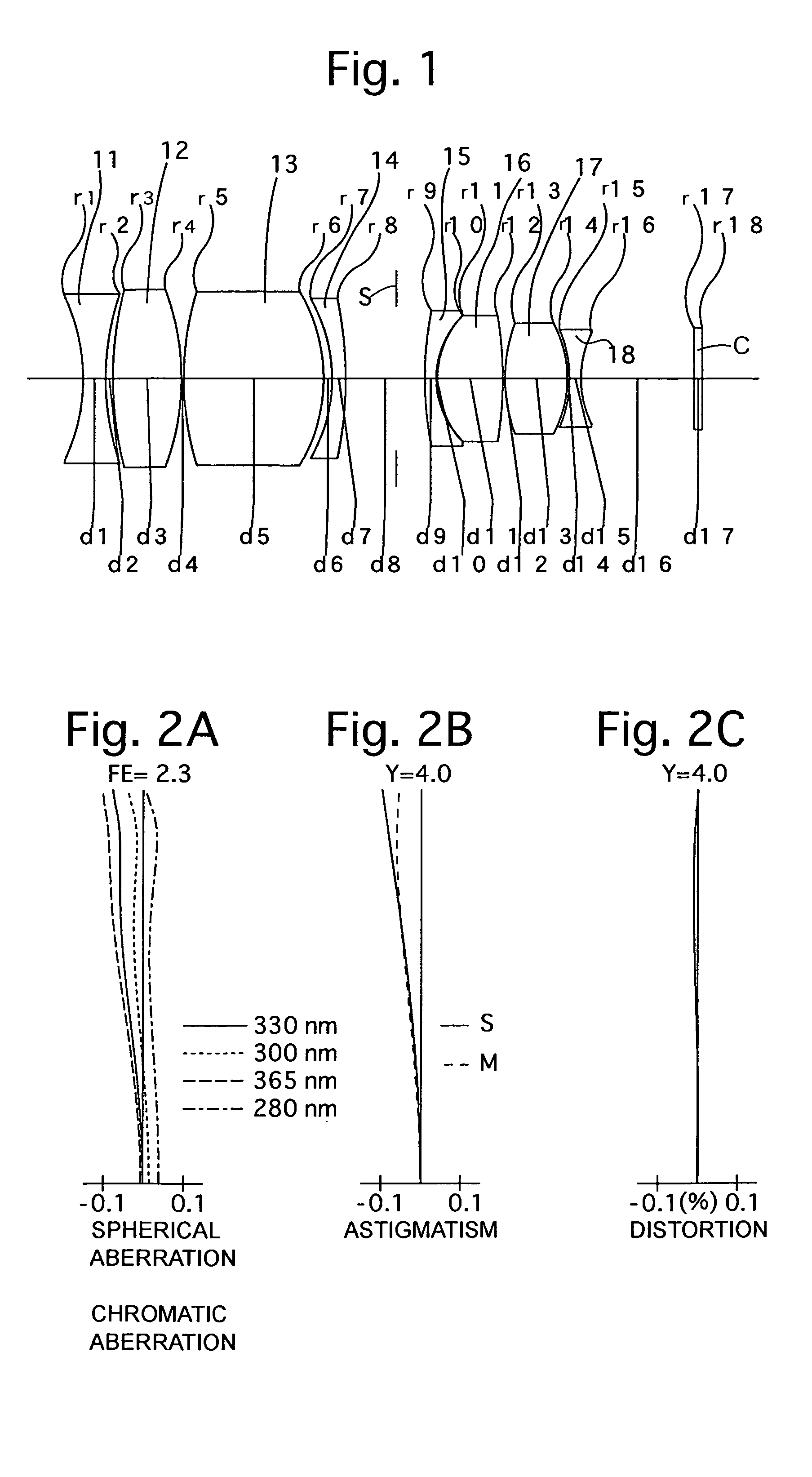
[0092]FIG. 1 is the lens arrangement of the ultraviolet imaging system, according to the first embodiment of the present invention. FIGS. 2A, 2B and 2C show aberrations occurred in the lens arrangement shown in FIG. 1 at the short focal length extremity. Table 1 shows the numerical data of the first embodiment.

[0093]A diaphragm S is provided 4.51 on the image side of the lens surface No. 8. The image plane is provided 3.95 behind lens surface No. 18. The base wavelength is 330 nm.

[0094]

TABLE 1FE = 1:2.3f = 24.96M = −0.100Y = 4.0fB = 14.46 (=10.00 + 0.75 / 1.48059 + 3.95)Surface No.rdGlass Material1−17.0782.00quartz223.4110.63331.7136.00fluorite4−22.7080.20526.67912.37fluorite6−15.0920.757−14.0931.20quartz8−35.3097.00931.6611.00quartz107.8000.10118.0565.80fluorite12−33.8970.201314.4415.54fluorite14−10.3290.2015−10.7831.00quartz169.03810.0017∞0.75quartz (plane-parallel plate)18∞—

embodiment 2

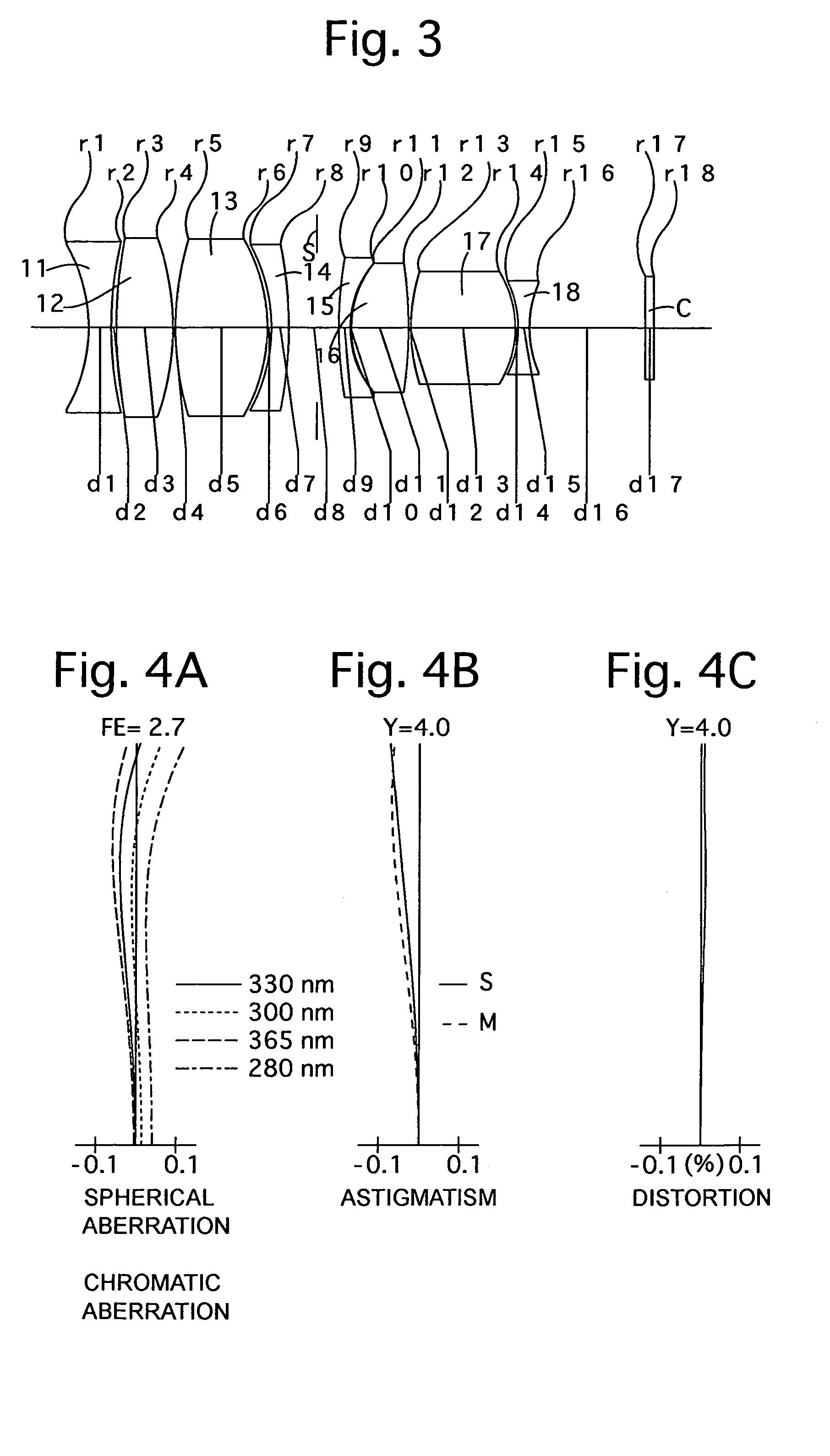
[0095]FIG. 3 is the lens arrangement of the ultraviolet imaging system, according to the second embodiment of the present invention. FIGS. 4A, 4B and 4C show aberrations occurred in the lens arrangement shown in FIG. 3 at the short focal length extremity. Table 2 shows the numerical data of the second embodiment.

[0096]A diaphragm S is provided 2.43 on the image side of the lens surface No. 8. The imaging plane is provided 4.07 behind lens surface No. 18. The base wavelength is 330 nm.

[0097]

TABLE 2FE = 1:2.7f = 24.90M = −0.100Y = 4.0fB = 14.58 (=10.00 + 0.75 / 1.48059 + 4.07)Surface No.rdGlass Material1−14.1391.98quartz232.4290.45340.3474.94fluorite4−22.9030.20527.0297.92fluorite6−15.4670.357−15.0681.50quartz8−36.3074.34935.8511.00quartz108.7060.10119.1014.94fluorite12−37.5100.201316.4089.14fluorite14−9.3000.2415−9.4461.00quartz169.88010.0017∞0.75quartz (plane-parallel plate)18∞—

embodiment 3

[0098]FIG. 5 is the lens arrangement of the ultraviolet imaging system, according to the third embodiment of the present invention. FIGS. 6A, 6B and 6C show aberrations occurred in the lens arrangement shown in FIG. 5 at the short focal length extremity. Table 3 shows the numerical data of the third embodiment.

[0099]A diaphragm S is provided 6.27 on the image side of the lens surface No. 8. The imaging plane is provided 3.95 behind lens surface No. 18. The base wavelength is 330 nm.

[0100]

TABLE 3FE = 1:2.5f = 24.95M = −0.100Y = 4.0fB = 14.46 (=10.00 + 0.75 / 1.48059 + 3.95)Surface No.rdLens Material1−12.9412.00quartz2−50.0000.203−54.1564.20fluorite4−15.2880.20531.1087.44fluorite6−14.6090.367−13.7631.20quartz81059.4918.13933.1931.00quartz108.7120.10118.8956.76fluorite12−25.0120.201311.1335.75fluorite14−11.9180.2015−11.5291.68quartz168.03710.0017∞0.75quartz (plane-parallel plate)18∞—

[0101]Table 4 shows the numerical values of each condition in each embodiment.

[0102]

TABLE 4Embod. 1Emod. 2...


PUM


Abstract

An ultraviolet imaging system includes at least two negative lens elements, and at least two positive lens elements. The ultraviolet imaging system satisfies the following conditions:−3<f(i=330) / r1<−0.5  (1)65<ν (ALL)  (2)0<ν(i=330) (P)−ν(i=330) (N)<10  (3)whereinf(i=330) designates the focal length of the entire ultraviolet imaging system with respect to a wavelength “i” of 330 nm (base wavelength);r1 designates the radius of curvature of the object-side surface of the most object-side lens element;ν (ALL) designates a reciprocal of a dispersion value, with respect to the d-line, of the glass material of all of the lens elements;ν(i=330) (P) designates the reciprocal of the dispersion value, for the positive lens elements, with respect to the wavelength of 330 nm; andν(i=330) (N) designates the reciprocal of the dispersion value, for the negative lens elements, with respect to the wavelength of 330 nm.

Description

BACKGROUND OF THE INVENTION[0001]1. Field of the Invention[0002]The present invention relates to an ultraviolet imaging system for use in an ultraviolet imaging apparatus, etc., and in particular, relates to an ultraviolet imaging system (photographing system) in which distortion is adequately corrected.[0003]2. Description of the Prior Art[0004]As an example of a conventional ultraviolet imaging system, a wide-angle lens system disclosed in Japanese Patent No.2858639 and Japanese Patent No.3042766 have been known; and a converging lens system disclosed in Japanese Unexamined Patent Publication No.Hei-10-104510 has been known. Note that a converging lens system generally has a narrower angle-of-view, and is used in a narrow-wavelength-band.[0005]The above-mentioned wide-angle lens system can attain a desirable imaging quality in a typical photographing operation; however, the correcting of distortion is not sufficiently made therein. Accordingly, a wide-angle lens system is not appr...

Claims


Application Information

Patent Timeline
Patent Type & Authority Patents(United States)
IPC IPC(8): G02B13/14G02B9/64
CPCG02B13/143
Inventor TADA, EIJIROHITO, TAKAYUKI
Owner RICOH IMAGING COMPANY
Why Eureka
Try Eureka