Charged-particle beam apparatus equipped with aberration corrector

a charge-particle beam and corrector technology, applied in the direction of instruments, magnetic discharge control, beam deviation/focusing by electric/magnetic means, etc., can solve the problems of insufficient consideration of the stability of the aberration correction system, the withstand voltage of the elements is exceeded, and the instrument is more susceptible to noise introduced, so as to achieve stably and optimal aberration correction and minimize the diameter of the probe

Active Publication Date: 2005-08-02
JEOL LTD
View PDF6 Cites 33 Cited by
  • Summary
  • Abstract
  • Description
  • Claims
  • Application Information

AI Technical Summary

Benefits of technology

[0027]In view of the foregoing, the present invention has been made. It is an object of the present invention to provide a charged-particle beam instrument which can perform aberration correction stably and optimally and minimize the diameter of a probe consisting of a charged-particle beam.

Problems solved by technology

However, it can be said that sufficient consideration has not been given to the stability of the aberration correction system, the range of the applied voltage, and optimum conditions from a viewpoint of commercialization.
As a result, there is a danger that the withstand voltage of the elements is exceeded.
As a result, the instrument is more susceptible to noise introduced in the accelerating voltage and variations in the power-supply voltage.
It is more difficult to correct aberration appropriately.
Therefore, the above-described phenomenon presents a problem in practical applications.
If this space, or distance, is simply secured, the following problems take place.
That is, the resultant aberrations of these higher orders increase in proportion to the distance between them.

Method used


Image

  • Charged-particle beam apparatus equipped with aberration corrector
  • Charged-particle beam apparatus equipped with aberration corrector
  • Charged-particle beam apparatus equipped with aberration corrector

Examples


first embodiment

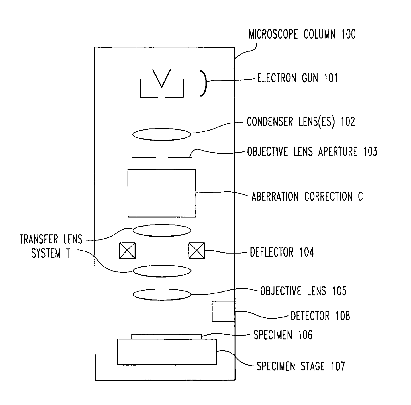
[0052]The preferred embodiments of the present invention are hereinafter described in detail by referring to the accompanying drawings. FIG. 5 shows the fundamental structure (first embodiment) of the present invention. This is an instrument for shooting a part of a charged-particle beam as a probe at a specimen and comprises four stages of electrostatic quadrupole elements 1, 2, 3, and 4 including two central quadrupole elements 2 and 3, two stages of magnetic quadrupole elements 5 and 6 for superimposing a magnetic potential distribution analogous to the electric potential distribution created by the two central quadrupole elements 2 and 3 on this electric potential distribution, an objective lens 7, transfer lenses 27a and 27b, an objective lens aperture 8 mounted in a part of the optical path, a manual input operation-and-display 9 having a display unit and permitting one to modify the accelerating voltage for imparting a given energy to the charged-particle beam and the working...

second embodiment

[0079]Accordingly, where the X- and Y-direction components of the aberration coefficients C5 and C3c cannot be made null at the same time, the operating conditions are so selected that blur of the particle probe is made as symmetrical as possible. That is, blur due to X-component and blur due to Y-component decrease to similar levels. The relation L1=L0 can be so selected that X- and Y-direction components become comparable to each other. This is used as the present invention. In practice, it is difficult to make the distance L1 variable. Therefore, the level of L0 is previously found by calculation or experiment and taken as a design distance L0. Furthermore, as shown in FIG. 6, focal length ƒb=ƒm giving a minimum value may be found, and the relation L1=L0 may be obtained by setting the distance L1 under this condition.

[0080]In the description of the first and second embodiments, the transfer lens system is made up of two stages. Similar advantages can be derived where a single-sta...

third embodiment

[0092]Supplementarily speaking, ƒa shown in FIG. 7 indicates the focal length of the transfer lens 27a adjacent to the aberration corrector C. In FIG. 8, the lens 27a does not exist and so the focal length of the transfer lens 27b is shown. That is, in the third embodiment shown in FIG. 8, ƒa of FIG. 7 corresponds to ƒb of FIG. 8, and the distance L1 of FIG. 7 corresponds to L2 of FIG. 8.

[0093]As described thus far, in the first, second, and third embodiments of the present invention, the aberration corrector C, the transfer lens 27b, and the objective lens 7 are set at the operating conditions which minimize the aberration coefficients C5 or C3c calculated by, or stored in, the manual input operation-and-display 9 from accelerating voltage Va, working distance WD, and probe current Ip set by the manual input operation-and-display 9.

[0094]In the configuration shown in the third embodiment of the present invention, where the length of the whole lens system is limited to a given lengt...


PUM


Abstract

A charged-particle beam instrument with an aberration corrector which comprises four stages of electrostatic quadrupole elements, two stages of magnetic quadrupole elements for superimposing a magnetic potential distribution analogous to the electric potential distribution created by the two central quadrupole elements of the four stages of electrostatic quadrupole elements on this electric potential distribution, and four stages of electrostatic octopole elements for superimposing an electric octopole potential on the electric potential distribution created by the four stages of electrostatic quadrupole elements.

Description

BACKGROUND OF THE INVENTION[0001]1. Field of the Invention[0002]The present invention relates to a charged-particle beam instrument equipped with an aberration corrector. The aberration corrector corrects aberrations, such as chromatic aberration and spherical aberration, in charged-particle beam optics that focus and direct a charged-particle beam at a specimen. The beam is produced in a scanning electron microscope, ion microprobe, or other similar apparatus.[0003]2. Description of Prior Art[0004]In scanning microscopes, transmission electron microscopes, and other apparatus, an aberration corrector is incorporated in the electron optics to enable high-resolution imaging or to enhance the probe current density. A system that corrects chromatic aberration by a combination of electrostatic quadrupole elements and magnetic quadrupole elements and corrects spherical aberration by four stages of octopole elements has been proposed as one example of the above-described aberration correc...

Claims


Application Information

Patent Timeline
Patent Type & Authority Patents(United States)
IPC IPC(8): H01J37/153H01J37/04G01Q40/00
CPCH01J37/153H01J2237/12
Inventor MATSUYA, MIYUKIHOSOKAWA, FUMIO
Owner JEOL LTD
Why Eureka
Try Eureka