

Electronic equipment and parameter adjusting method
A technology of electronic equipment and students, applied in the direction of cathode ray tube indicators, static indicators, instruments, etc., can solve the problem of high cost
- Summary
- Abstract
- Description
- Claims
- Application Information
AI Technical Summary
Problems solved by technology
Method used
Image

Examples
Embodiment 1
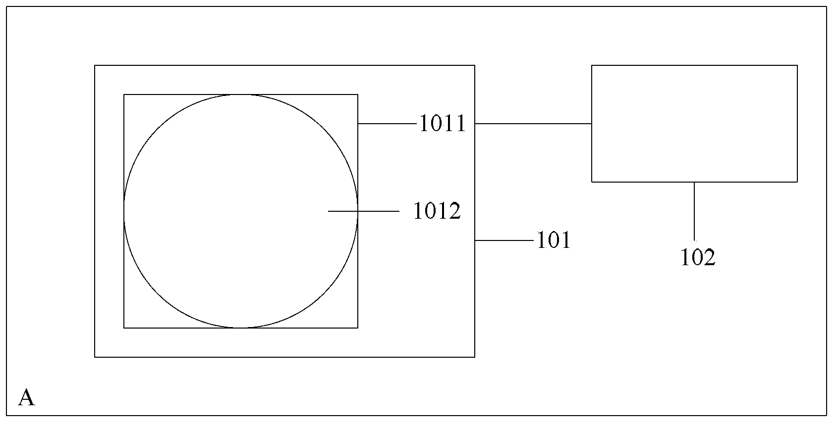
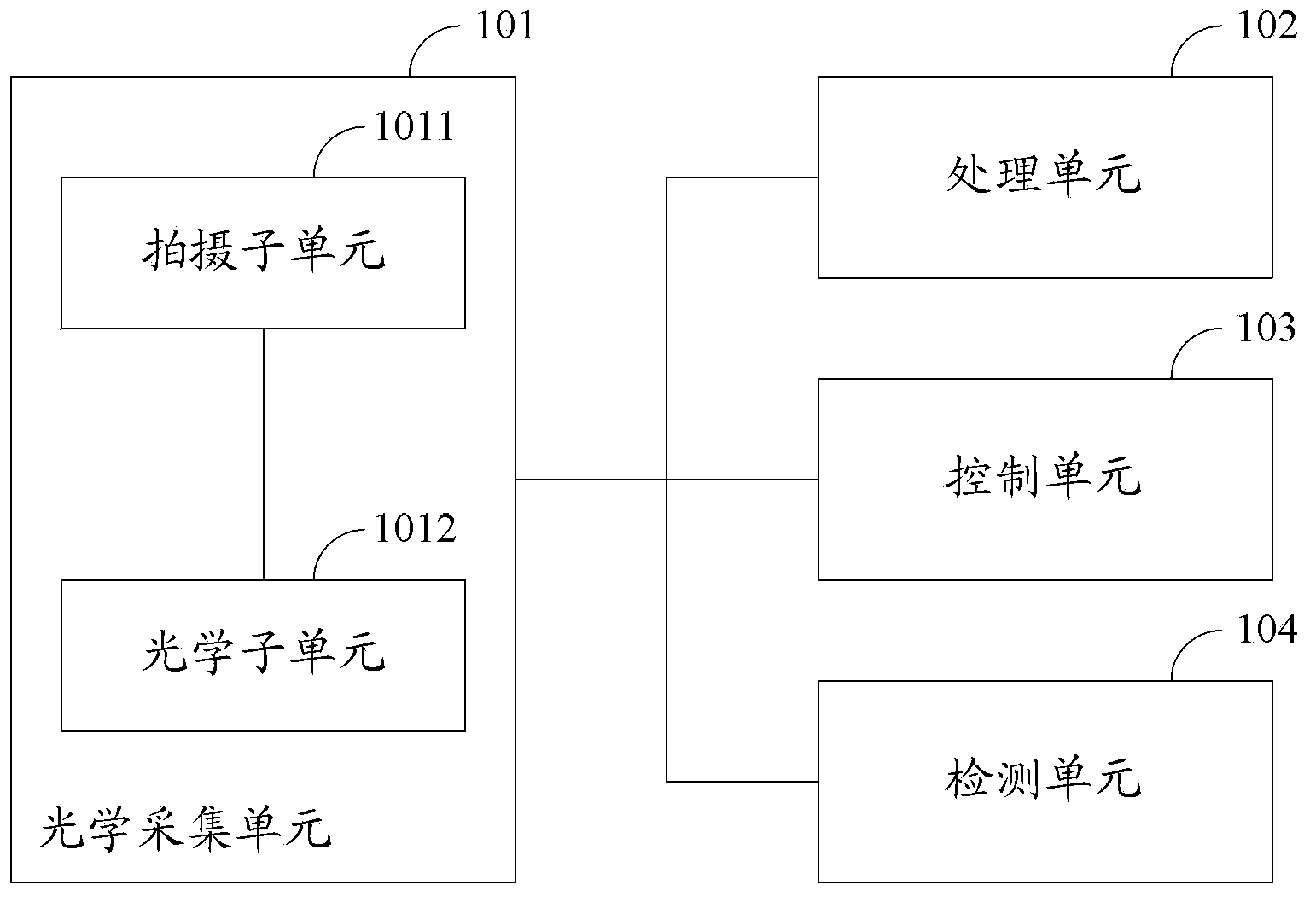
[0042] See Figure 1A , an embodiment of the present invention provides an electronic device, the electronic device may have a display unit, and the electronic device may further include an optical collection unit 101 and a processing unit 102 .
[0043] In the embodiment of the present invention, the optical collection unit 101 may include a photographing subunit 1011 and an optical subunit 1012, wherein the optical subunit 1012 may be attached to the front end of the photographing subunit 1011, that is, the end of the photographing subunit 1011 facing the surrounding environment .
[0044] Figure 1A Among them, A represents the electronic equipment.
[0045] in, Figure 1A is just an example, and does not represent the actual specific shape and structure of the electronic device and each functional unit.
[0046] In the embodiment of the present invention, the optical subunit 1012 may at least have a scattering state. When the optical subunit 1012 is in the scattering sta...
Embodiment 2
[0099] See Figure 4 , the embodiment of the present invention provides a parameter adjustment method, the method can be applied to an electronic device, the electronic device can have a display unit, the electronic device can also include an optical acquisition unit 101, the optical acquisition unit 101 can include a camera The unit 1011 and the optical subunit 1012 attached to the outside of the photographing subunit 1011, the optical subunit 1012 may have a scattering state. The main process of the method is as follows:
[0100] Step 401: When the optical subunit 1012 is in the scattering state, collect ambient light information through the optical collection unit 101 .
[0101] In the embodiment of the present invention, the photographing subunit 1011 may be a camera in the electronic device, or may be other functional units with a photographing function.
[0102] In the embodiment of the present invention, the optical subunit 1012 may have the scattering state. When th...
Embodiment 3
[0119] The electronic device is a mobile phone, and the mobile phone has a display unit and a camera, and the camera is the photographing subunit 1011 of the optical collection unit 101 of the mobile phone. In the embodiment of the present invention, a thin film is attached on the outside of the photographing sub-unit 1011, and the film is the optical sub-unit 1012. In the embodiment of the present invention, the optical sub-unit 1012 can have a scattering state and a non-scattering state. When the optical subunit 1012 is in the scattering state, the optical subunit 1012 can be equivalent to a scattering sheet, and when the optical subunit 1012 is in the non-scattering state, the optical subunit 1012 can be equivalent to a transparent lens.
[0120] Preferably, before the ambient light information is collected by the optical collection unit 101, it may first be determined whether the optical sub-unit 1012 is in the scattering state. In the embodiment of the present invention, ...
PUM
 Abstract
Description
Claims
Application Information