

Chip removing machining cutter, cutting board clamping blades and replaceable blade
A technology of cutting inserts and tools, applied in cutting inserts, tool holders, accessories of tool holders, etc., can solve the problem of not effectively reaching the rake face of cutting inserts.
- Summary
- Abstract
- Description
- Claims
- Application Information
AI Technical Summary
Problems solved by technology
Method used
Image

Examples
Embodiment Construction
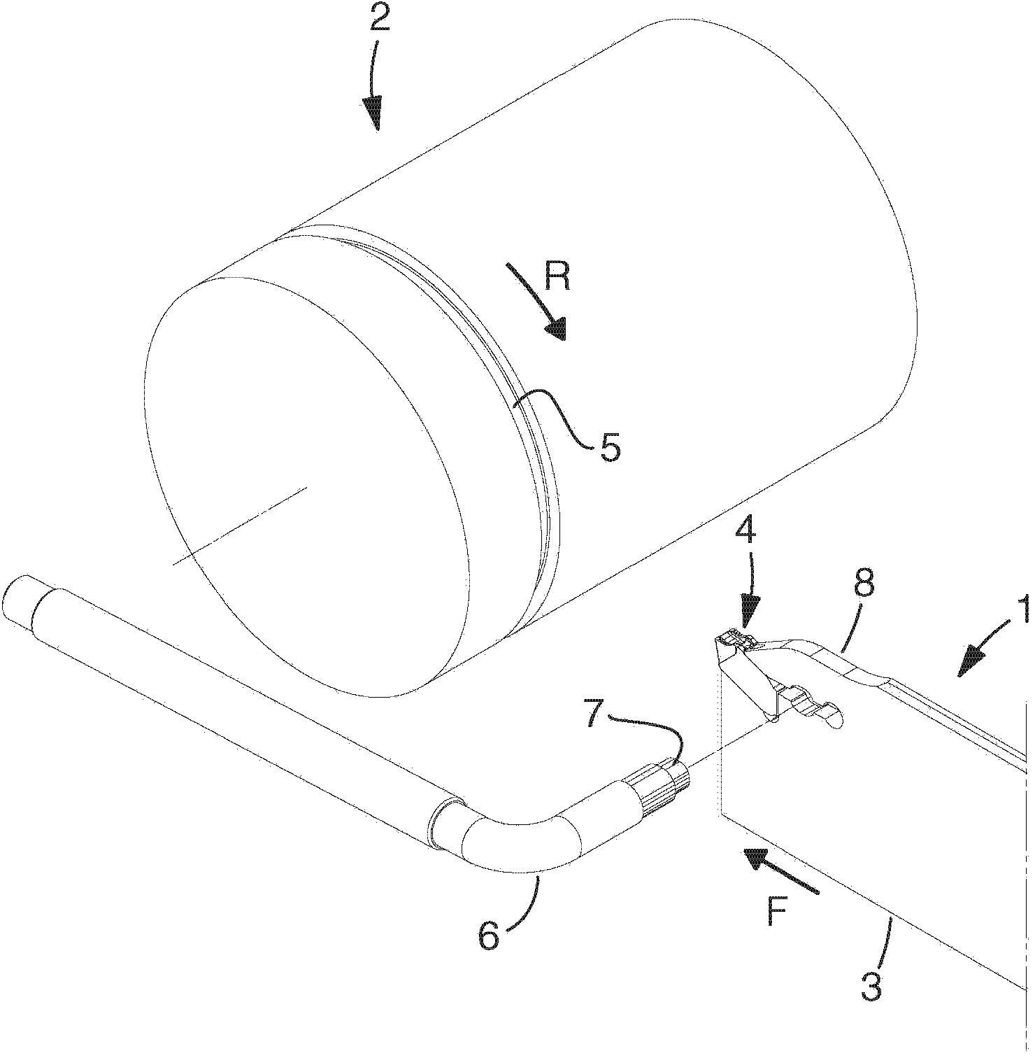
[0035] exist figure 1 In , a tool 1 according to the invention is shown in connection with the machining of a workpiece 2 . The tool is realized in the form of a turning tool, the main part of which is the blade plate 3 which serves as a holder or base body for an exchangeable cutting insert 4 . The workpiece 2 is cylindrical and rotatable in the direction of rotation R. As shown in FIG. By feeding the tool 1 longitudinally in the feed direction F during simultaneous rotation of the workpiece, a circumferential groove 5 can be provided in the envelope surface of the workpiece, the width of which is determined by the width of the main cutting edge comprised in the cutting insert 4 , while the depth of the groove 5 is determined by how far the blade and its cutting inserts are fed into the workpiece.
[0036] figure 1 The processing method illustrated in is a grooving operation.
[0037] exist figure 1 , also shows a key 6 with an eccentric body 7 by means of which a clamp...
PUM
 Abstract
Description
Claims
Application Information