Lathe spindle center spraying cooling device

Inactive Publication Date: 2013-09-25
SHENYANG NO MACHINE TOOL FACTORY
View PDF7 Cites 4 Cited by
  • Summary
  • Abstract
  • Description
  • Claims
  • Application Information

AI Technical Summary

Problems solved by technology

[0002] Chip control and chip removal are long-standing problems when machining the inner hole of a CNC lathe. The conventional cooling method is to flush the coolant from the processing end of the part inward, which is inconsistent with the chip removal direction of the part and affects chip removal. As a result, it is difficult to discharge chips, and it is easy to scratch the surface of the part, reducing the machining accuracy of the inner hole

Method used


Image

  • Lathe spindle center spraying cooling device

Examples


Embodiment Construction

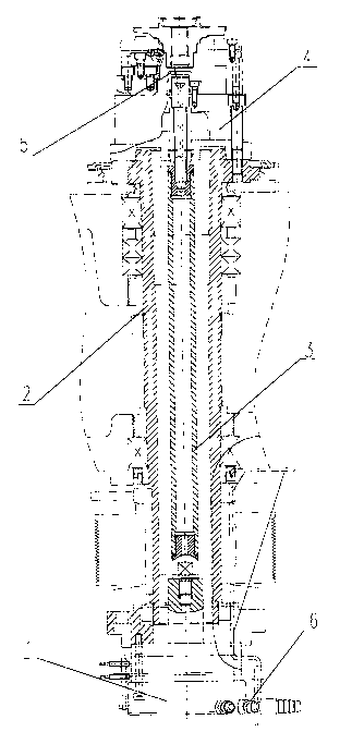
[0008] Aiming at the present situation that the inner holes of parts processed by CNC lathes are mostly cooled by the processing end, the chip removal effect is not smooth, and the machining accuracy of the inner holes is not well maintained. , pipe joint 6 and other components, to achieve inner hole cooling from the clamping end of the part. The oil cylinder is assembled on the rear end of the lathe spindle through bolts, and the two ends of the hollow tie rod are connected with the hollow piston rod of the oil cylinder and the connecting rod in the center of the chuck in a threaded manner, and the sealing ring is used to seal the screw thread to prevent the cooling water from leaking into the main shaft ;The chuck is installed on the front end of the main shaft through bolts, the nozzle and the chuck are connected by bolts, and the sealing ring is used to seal the threaded part. The nozzles can be designed into different shapes according to the various needs of the proces...


PUM


Abstract

The invention provides a lathe spindle center spraying cooling device which aims at solving the problem that when a digital controlled lathe is used for machining an inner hole of a part, cooling liquid carries out washing to the inside from the machining end of the part, and the washing direction is different from the swarf discharging direction of the part. The lathe spindle center spraying cooling device is characterized in that an oil cylinder is assembled at the back end of a lathe spindle, the two ends of a hollow pulling rod are connected with a hollow piston rod of the oil cylinder and a connecting rod in the center of a chuck respectively, the chuck is installed at the front end of the spindle through a bolt, a spraying nozzle is connected with the chuck through a bolt, all threaded rotary connecting parts are sealed by sealing rings, and a pipe connector is installed on the oil cylinder. Cooling water sequentially passes through the pipe connector, the oil cylinder, the pulling rod in the center of the spindle, the chuck and the spraying nozzle to be sprayed on the inner hole of the part. The lathe spindle center spraying cooling device has the advantages that the spraying direction of the cooling water is the same as the swarf discharging direction, and the swarf discharging efficiency is improved.

Description

technical field [0001] The invention relates to a lathe cooling device. Background technique [0002] Chip control and chip removal are long-standing problems when CNC lathes process the inner holes of parts. The conventional cooling method is to flush the coolant from the processing end of the part inward, which is inconsistent with the chip removal direction of the part and affects chip removal. As a result, it is difficult to discharge chips, and it is easy to scratch the surface of the part, reducing the machining accuracy of the inner hole. Contents of the invention [0003] The object of the present invention is to provide a spray cooling device for the center of the lathe spindle, which cools the inner hole of the part from the direction of the clamping end of the part, and can solve the above problems. [0004] The object of the present invention is achieved like this: it comprises lathe main shaft, it is characterized in that: oil cylinder is assembled on the rea...

Claims


Application Information

Patent Timeline
Patent Type & Authority Applications(China)
IPC IPC(8): B23Q11/10
Inventor 王家兴盖立亚白平宋威白雪松薛佟邹滢孔祥志刘守胜郭金彪宋宇王东辉
Owner SHENYANG NO MACHINE TOOL FACTORY
Why Eureka
Try Eureka