Tool holder and metal cutting insert with chip breaking surfaces

a tool holder and metal cutting technology, applied in the field of metal working, can solve the problems of unbalanced tool centerline, difficult control of chips during cutoff operation, and inherently difficult ductile steels, and achieve the effect of improving chip control

Active Publication Date: 2011-02-08
KENNAMETAL INC
View PDF60 Cites 44 Cited by
  • Summary
  • Abstract
  • Description
  • Claims
  • Application Information

AI Technical Summary

Benefits of technology

[0007]The present invention provides a new and improved cutting insert for cutting metal which provides multiple chip breaking surfaces, the configuration of which are especially effective when cutting low strength, ductile steels. The multiple chip breaking surfaces are also effective in improving chip control in a cutting insert having a cutting edge oriented at a lead angle. In the preferred and illustrated embodiment, the cutting insert includes a pair of rake surfaces that extend from a forward cutting edge to a pair of associated first chip breaking surfaces. A pair of second chip breaking surfaces are positioned downstream of the first chip breaking surfaces and are separated by a transition surface. The first chip breaking surfaces impart an initial curl to the chip as it leaves the cutting edge of the tool.

Problems solved by technology

Known cutting insert designs, when used on low strength, ductile steels inherently experience several problems.
The task of controlling chips during a cutoff operation is made more difficult when a lead angle is employed to ensure that the manufactured part is cleanly severed from the tube and bar stock.
Techniques have included a chip breaker which was unbalanced about the centerline of the tool, such that it opposed a spiraling tendency.
While these techniques were sufficient on some jobs, they tended to be very limited in range and frequently increased cutting pressure to obtain chip control, sacrificing tool life in the process.
When this type of insert is mounted in the type of tool holder described above, the planar tool holder backup locating surface which securely supports grooving or straight cutoff inserts will no longer be able to offer a large contact area, but much weaker and less dimensionally consistent line contact.
These techniques have not been totally satisfactory and, in some cases, added unwanted expense to the cost of manufacturing the insert.

Method used


Image

  • Tool holder and metal cutting insert with chip breaking surfaces
  • Tool holder and metal cutting insert with chip breaking surfaces
  • Tool holder and metal cutting insert with chip breaking surfaces

Examples


Embodiment Construction

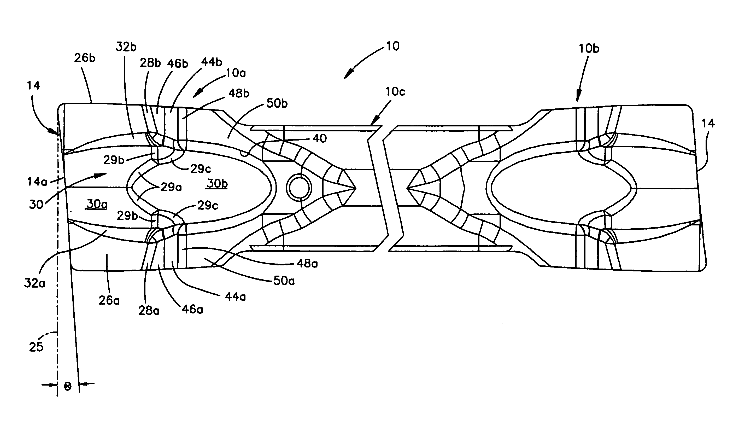
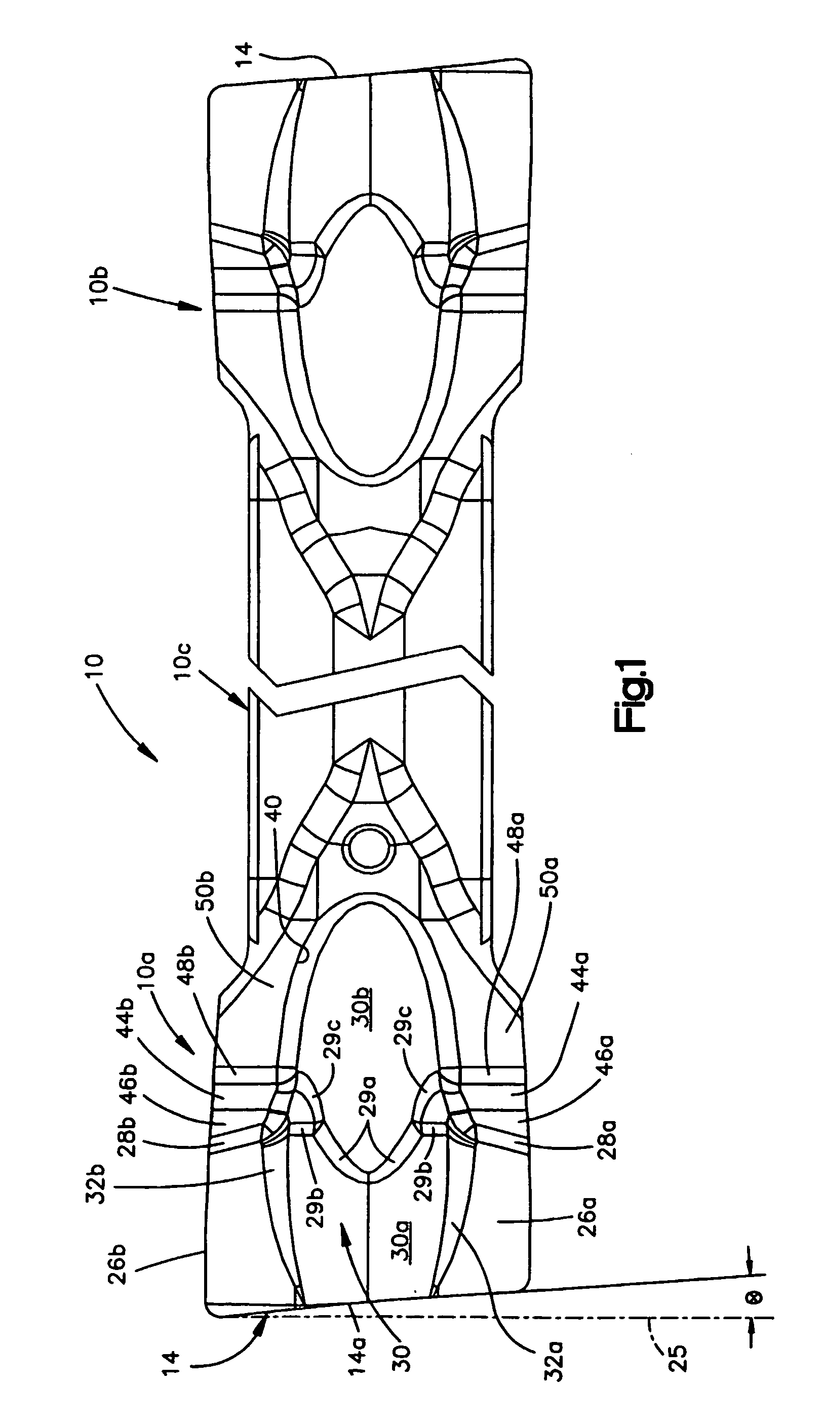
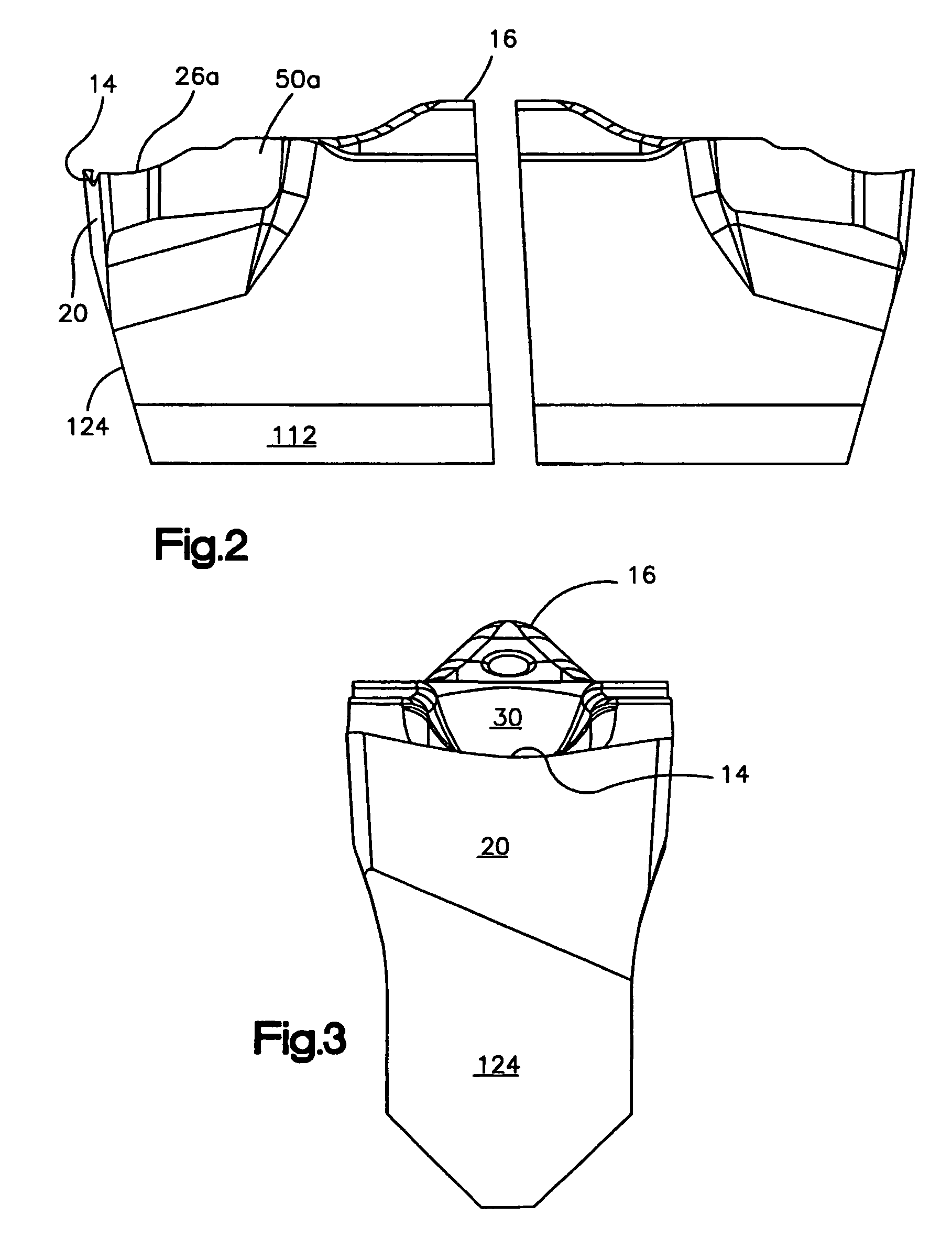
[0024]FIGS. 1-4 illustrate the overall construction of a metal cutting insert 10 constructed in accordance with the preferred embodiment of the invention. In use, the insert 10 is clamped in a tool holder 100 (see FIG. 6). Typically, the tool holder forms part of a slide mechanism which positions a cutting edge 14 of the cutting insert 10 into contact with a rotating workpiece (not shown) in order to perform a cutting operation on the workpiece.

[0025]In the disclosed embodiment, the insert 10 includes a pair of cutting portions 10a, 10b disposed on either side of a shank portion 10c. In use, the shank portion 10c of the insert 10 is clamped to the tool holder 100 (shown in FIG. 6) which locates and supports one of the cutting portions, i.e., 10a at a machining position. When the one cutting portion 10a is worn, the insert 10 is rotated 180° in the tool holder 100 in order to locate the other cutting portion 10b at the machining position. As seen best in FIGS. 2 and 3, the insert 10 ...


PUM

PropertyMeasurementUnit
diameteraaaaaaaaaa
transverse dimensionaaaaaaaaaa
lead angleaaaaaaaaaa

Abstract

A metal cutting insert (10) having a pair of cutting portions (10a, 10b) disposed on either end of a shank portion (10c), each cutting portion having a front clearance face (20), the upper boundary of which defines a cutting edge (14). A pair of spaced apart chip breaking surfaces (26a, 26b, 28a, 28b) commence at or near the cutting edge and extend away from the cutting edge. A pair of secondary chip breaking surfaces (44a, 44b, 46a, 46b, 48a, 48b, 50a, 50b) are located downstream of the first chip breaking surfaces and are interconnected with associated first chip breaking surfaces by transition surfaces. A center channel (30) is located between the chip breaking surfaces and includes an entry portion (30a). A tool holder (100) includes a base (102) and clamping arm (104) which together define a gap (106) for receiving one of the cutting portions of the insert.

Description

TECHNICAL FIELD[0001]The present invention relates generally to metal working and, in particular, to a metal cutting insert and a tool holder for holding a metal cutting insert.BACKGROUND ART[0002]Metal cutting inserts having a variety of chip controlling shapes are known in the art. U.S. Pat. No. 3,654,681 discloses a metal cutoff tool characterized by the fact that the cutting portion thereof is provided with a chip breaker surface that includes opposed chamfer surfaces located rearwardly of the cutting edge that assist in providing clearance for chip removal purposes. U.S. Pat. No. 3,815,191 teaches a chip forming insert that imparts a longitudinally extending bulge to a chip which stiffens the chip and modifies its form. U.S. Pat. No. 3,973,308 teaches a cutting tool that has several depressions or notches separated from each other and situated inside and spaced from the cutting edge. U.S. Pat. No. 4,629,372 to Huston discloses a cutting insert having a chip breaking surface tha...

Claims


Application Information

Patent Timeline
Patent Type & Authority Patents(United States)
IPC IPC(8): B23B27/04B23B29/04B23PB26D3/00
CPCB23B27/045B23B29/043B23B2200/087B23B2200/202Y10T407/24Y10T407/235Y10T407/245Y10T407/23B23B2205/02
Inventor SIMPSON, III, VANDELLTONG, NELSON PAO CHUNG
Owner KENNAMETAL INC
Why Eureka
Try Eureka