Automated transmission control apparatus

A technology of automatic transmission and control equipment, which is applied in the direction of transmission control, mechanical equipment, components with teeth, etc., and can solve the problem of time-consuming gear stages

Inactive Publication Date: 2014-12-31
AISIN SEIKI KK
View PDF1 Cites 2 Cited by
  • Summary
  • Abstract
  • Description
  • Claims
  • Application Information

AI Technical Summary

Problems solved by technology

As a result, additional drive power is required and ...

Method used


Image

  • Automated transmission control apparatus
  • Automated transmission control apparatus
  • Automated transmission control apparatus

Examples


Embodiment Construction

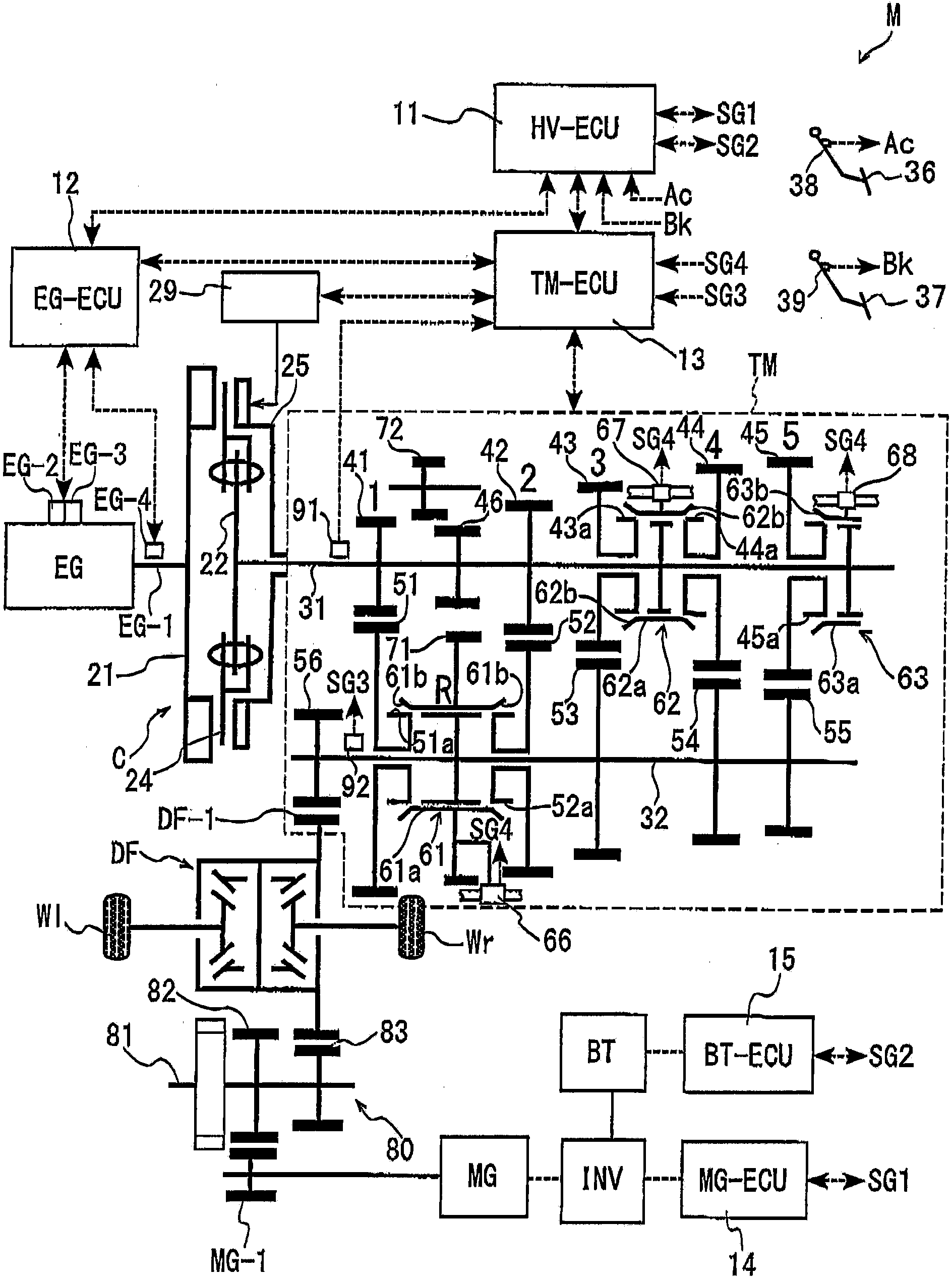
[0024] The first embodiment will be explained with reference to the drawings. In the first embodiment, an automatic transmission including the automatic transmission control apparatus according to the first embodiment is applied to a hybrid vehicle (hereinafter will be referred to as a vehicle M). figure 1 is a schematic diagram showing the configuration of the vehicle M. FIG. Such as figure 1 As shown, the vehicle M includes an engine EG, a motor generator MG, a clutch C, a transmission TM (hereinafter referred to as TM), an inverter INV, a battery BT, a hybrid electronic control unit (ECU) 11 (in HV -ECU), engine ECU12 (denoted by EG-ECU), TM ECU13, motor ECU14 (denoted by MG-ECU), battery ECU15 (denoted by BT-ECU), and speed reducer 80. In vehicle M, drive wheels WI, Wr are driven by rotational torque output from engine EG and motor MG.

[0025]The vehicle M includes an accelerator pedal 36 (ie, accelerator) and a brake pedal 37 (ie, brakes). Operating the accelerator p...


PUM


Abstract

An automated transmission control apparatus includes an accelerated/decelerated travelling determination portion (11) determining a decelerated travelling state and an accelerated traveling state, a gear stage determination portion (13) determining a gear stage to be changed to, on the basis of at least one down-shift curve, on the basis of a travelling state, and a shift operation control portion (13) controlling a clutch actuator (29) in a case where the accelerated/decelerated travelling determination portion determines a sudden braking state, the shift operation control portion controlling the shift actuator to move at least one sleeve (61 a, 62a, 63a) to a neutral position in a case where the gear stage determination portion determines that the down-shift curve is crossed, the shift operation control portion maintaining all the sleeves in a stand-by state at the neutral position while the accelerated/decelerated travelling determination portion maintains the determination of the sudden braking state.

Description

technical field [0001] The present disclosure generally relates to an automatic transmission control apparatus. Background technique [0002] In order to transmit rotation and / or torque from a driving device such as an engine and / or an electric motor to drive wheels according to the driving environment of the vehicle, a conventional power system of a vehicle is provided with a transmission for changing the rotation of the driving device torque and / or speed. Some types of transmissions (such as the known conventional meshing type) in which a plurality of idler gears (idler gears) cooperating with the rotating shafts are connected to the drive wheels so that the idler gears can rotate relative to the rotating shafts and in the axial direction of the rotating shafts The top is immovable, and a plurality of gears provided at a counter shaft arranged in parallel with the rotation shaft always mesh with each other. According to a known conventional meshing type transmission, a s...

Claims


Application Information

Patent Timeline
IPC IPC(8): F16H59/44F16H63/00
CPCF16H61/0213F16H59/54F16H63/46F16H2061/168F16H2312/18
Inventor 原田新也村上芳弘谷本英一
Owner AISIN SEIKI KK
Why Eureka
Try Eureka