Male connector equipped with lock mechanism

A male connector, locking mechanism technology, applied in the direction of sleeve/socket connection, coupling, connecting pipe, etc., can solve the problem that the male connector 900 remains unstable

Active Publication Date: 2014-12-31
JMS CO LTD
View PDF10 Cites 1 Cited by
  • Summary
  • Abstract
  • Description
  • Claims
  • Application Information

AI Technical Summary

Problems solved by technology

At this time, since the male connector 900 is held only by two fingers abutting against the two operation parts 935, there is a problem that the holding of the male connector 900 becomes unstable.

Method used


Image

  • Male connector equipped with lock mechanism
  • Male connector equipped with lock mechanism
  • Male connector equipped with lock mechanism

Examples


Embodiment approach 1

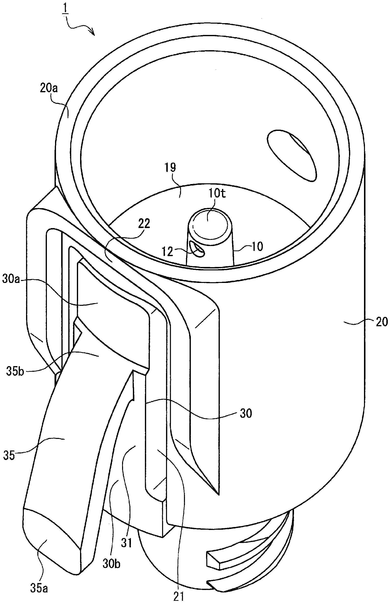
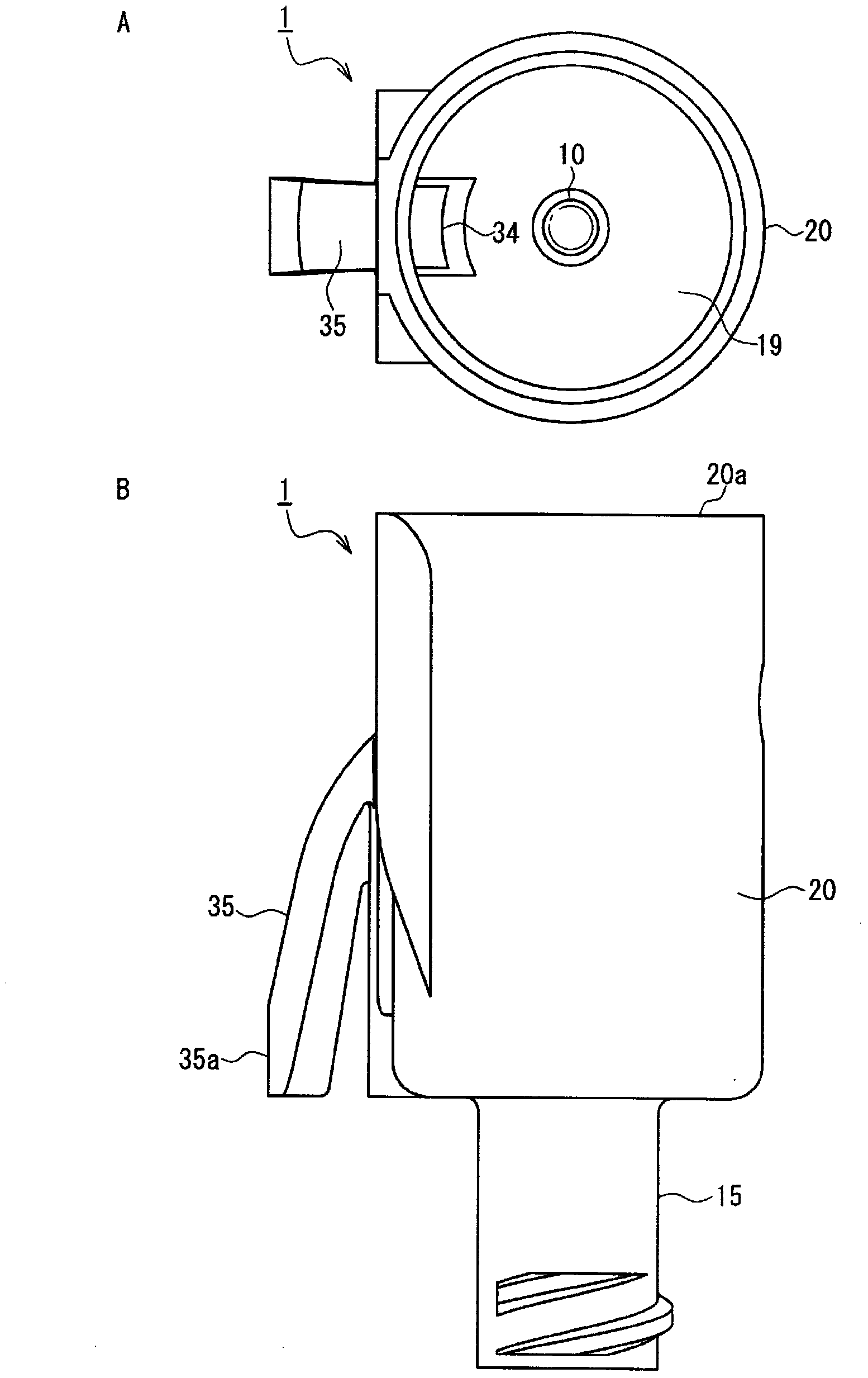
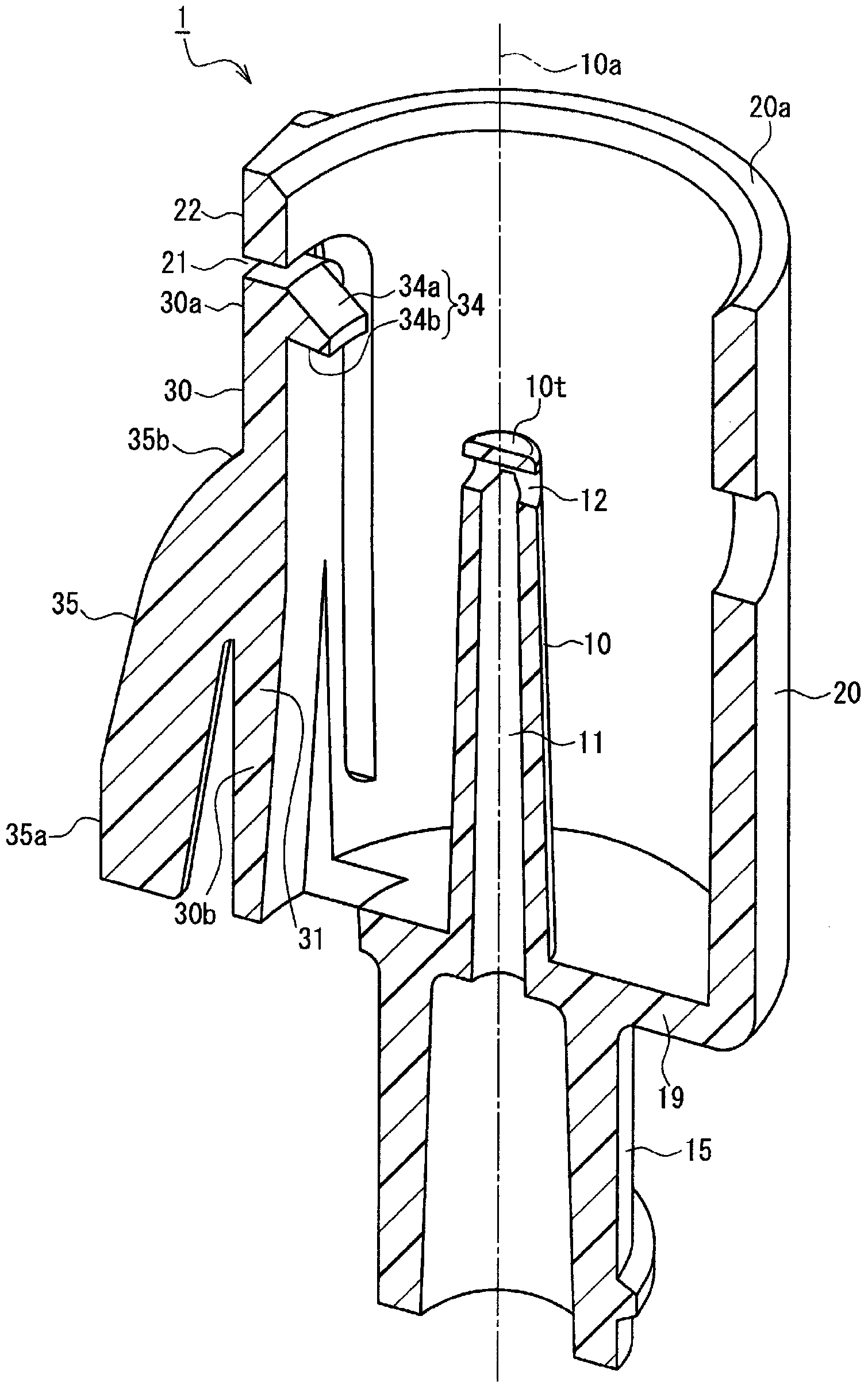
[0046] figure 1 It is a perspective view of a male connector with a lock mechanism (hereinafter simply referred to as a "male connector") 1 according to Embodiment 1 of the present invention. figure 2 A is a top view of the male connector 1, figure 2 B is a side view of the male connector 1 . also, image 3 It is a cross-sectional perspective view of the male connector 1 .

[0047] The male connector 1 according to Embodiment 1 includes a rod-shaped male guide 10 as a male component. exist image 3 Among them, 10a is the central axis of the male inducer 10. Hereinafter, for convenience of explanation, the longitudinal direction (direction parallel to the central axis 10a) of the male-type inducer 10 is referred to as the "up-and-down direction", and the direction perpendicular to the longitudinal direction of the male-type inducer 10 is referred to as the "horizontal direction". . In addition, in the up-down direction, the side closer to the base 19 is called "lower ...

Embodiment approach 2

[0080] Figure 9 It is a perspective view of a male connector with a locking mechanism (hereinafter simply referred to as a "male connector") 2 according to Embodiment 2 of the present invention. The male connector 2 of Embodiment 2 differs from the male connector 1 of Embodiment 1 in that: On the shield 20 , an end edge 20 a from the upper side thereof is formed parallel to the male guide member 10 . A pair of cutouts 23 extending toward the abutment 19 . The pair of cutouts 23 face each other across the male guide 10 , and the direction in which the pair of cutouts 23 face each other is substantially perpendicular to the direction in which the locking lever 30 and the male guide 10 face each other.

[0081] The usage and operation of the male connector 2 according to the second embodiment configured as above will be described.

[0082] Figure 10 It is a perspective view showing the male connector 2 and the needleless interface 200 as the female connector before connectio...


PUM


Abstract

This lock mechanism is provided with the following: a hood (20), disposed to as to surround a male member (10), into which a male connector (100) is inserted; and a single locking lever (30) with a cantilevered support structure that allows elastic displacement. The locking lever (30) is disposed such that the lengthwise direction thereof is substantially parallel to the male member (10), with the free end (30a) of the locking lever (30) being on the tip side of the male member (10) and the fixed end (30b) of the locking lever (30) being on the base side of the male member (10). The locking lever (30) is provided with a prong (34) that engages with the male connector (100). A manipulation arm (35) protrudes from the surface of the locking lever (30) on the opposite side thereof from the male member (10) and extends toward the fixed end (30b) of the locking lever (30). When the tip (35a) of the manipulation arm (35) is subjected to a pressing force directed towards the male member (10), the locking lever (30) elastically displaces such that the prong (34) moves away from the male member (10).

Description

technical field [0001] The present invention relates to a male connector provided with a locking mechanism for maintaining the connection state of the male connector and the female connector. Background technique [0002] When infusion or blood transfusion is performed on a patient, or extracorporeal blood circulation is performed during surgery, it is necessary to form a path (transfer line) for transporting a liquid such as a medical solution or blood. The transfer line is generally formed by connecting containers, various instruments, liquid delivery pipes, and the like. In addition, when injecting the medical solution administered to the patient into the medical solution bag (container), it is necessary to connect the medical solution bag and the syringe, and the like. In this way, a male connector and a female connector are used to detachably connect different components to each other. [0003] As an example of a female connector used for this purpose, a needle-less p...

Claims


Application Information

Patent Timeline
IPC IPC(8): A61M39/02A61J1/14
CPCA61M39/045A61M39/1011A61M2039/1027F16L21/08F16L37/086
Inventor 冲山忠
Owner JMS CO LTD
Why Eureka
Try Eureka