Floating vehicle fixture for differential shell and clamping method

A differential and floating technology, which is applied in the field of floating car fixtures and clamping for differential housings, can solve problems affecting the yield, workpiece shaking, and difficulty in ensuring distance dimensions, etc., to ensure smoothness and accurate positioning The effect of reducing the accumulation of iron filings and facilitating the smooth discharge

Active Publication Date: 2015-01-07
CRRC CHANGZHOU AUTO PARTS CO LTD +1
View PDF6 Cites 2 Cited by
  • Summary
  • Abstract
  • Description
  • Claims
  • Application Information

AI Technical Summary

Problems solved by technology

Since the differential housing generally has a symmetrical structure with two windows, the design of the parting surface is relatively complicated, which causes certain difficulties in the selection of machining positioning points. The distance from the blank surface at the top of the two windows to the machining end surface also difficult to guarantee
Conventional lathe fixtures use standard chucks to clamp workpieces, and it is difficult to completely avoid the parting lin

Method used


Image

  • Floating vehicle fixture for differential shell and clamping method
  • Floating vehicle fixture for differential shell and clamping method
  • Floating vehicle fixture for differential shell and clamping method

Examples


Example Embodiment

[0031] The technical solutions in the embodiments of the present invention will be clearly and completely described below in conjunction with the accompanying drawings in the embodiments of the present invention. Obviously, the described embodiments are only a part of the embodiments of the present invention, rather than all the embodiments. Based on the embodiments of the present invention, all other embodiments obtained by those of ordinary skill in the art without creative work fall within the protection scope of the present invention.
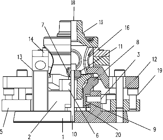
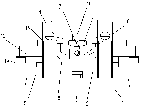
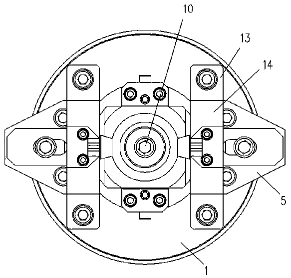
[0032] Such as Figure 1~6 As shown, this embodiment discloses a floating vehicle clamp for a differential housing. The differential housing 15 has an axially penetrating central hole 18, a pair of windows 16 symmetrically opened on the spherical side wall of the differential housing, and a pair of small sink grooves arranged perpendicular to the direction of the windows. 17.

[0033] The floating lathe clamp for the differential housing inclu...


PUM


Abstract

The invention provides a floating vehicle fixture for a differential shell. The floating vehicle comprises a lathe chuck, a first locking component and a second locking component, the lathe chuck is provided with a base plate and an upper plate. An axially movable floating sleeve is placed into the upper plate, a pair of fixing blocks are symmetrically arranged on the upper plate, a positioning column is arranged on each fixing block and extends into a small sinking trough of the differential shell, the first locking component is arranged in the floating sleeve and extends into a center hole of the differential shell, and the second locking component is fixed onto the lathe chuck, extends from a window of the differential shell and is used for pressing the lower edge of the window. By the aid of the floating sleeve, a spherical side wall of the differential shell is supported by the floating sleeve, and three springs are arranged below the floating sleeve, so that the floating sleeve clings to a workpiece. By the aid of the first locking component and the second locking component, a workpiece is preliminarily and mainly clamped, so that the workpiece is clamped by the vehicle fixture.

Description

technical field [0001] The invention relates to a mechanical clamp, in particular to a floating vehicle clamp for a differential housing and a clamping method. Background technique [0002] In the processing of the automobile differential case, starting from the structural characteristics of the workpiece itself, the first process is often processed by lathe equipment. According to drawing requirements, lathe fixtures need to adopt casting features to ensure dimensional accuracy. Since the differential housing is generally a symmetrical structure with two windows, the design of the parting surface is relatively complicated, which causes certain difficulties in the selection of machining positioning points. The distance from the blank surface at the top of the two windows to the machining end surface It is also difficult to guarantee. Conventional lathe fixtures use standard chucks to clamp workpieces, and it is difficult to completely avoid the parting line of castings dur...

Claims


Application Information

Patent Timeline
IPC IPC(8): B23Q3/12
CPCB23Q3/12
Inventor 尚付成谷春春王翠玲陈佳
Owner CRRC CHANGZHOU AUTO PARTS CO LTD
Why Eureka
Try Eureka