A device and method for simulating the formation of cracks in initially solidified slabs in continuous casting crystallizers

A continuous casting crystallizer and simulation device technology, which is applied to measuring devices, instruments, scientific instruments, etc., can solve the problems that it is impossible to propose targeted preventive measures, it is difficult to study the crack mechanism of the solidified slab shell, and the cracks cannot be simulated. Accurate and controllable temperature, low experiment cost and convenient experiment process

Active Publication Date: 2016-09-28
CENT SOUTH UNIV
View PDF6 Cites 0 Cited by
  • Summary
  • Abstract
  • Description
  • Claims
  • Application Information

AI Technical Summary

Problems solved by technology

[0004] The technical problem to be solved by the present invention is to provide a device and method for simulating the formation of cracks in the initial solidification billet in the continuous casting crystallizer in the iron and steel production process in view of the deficiencies in the prior art, so as to solve the problem of the steel cracks in the mold in the existing iron and steel metallurgical continuous casting process. The initial solidification of the shell is subjected to various forces including thermal stress, molten steel static pressure, friction, etc., and cracks cannot be simulated, making it difficult to study the mechanism of cracks in the solidified shell, and it is impossible to propose targeted preventive measures

Method used


Image

  • A device and method for simulating the formation of cracks in initially solidified slabs in continuous casting crystallizers
  • A device and method for simulating the formation of cracks in initially solidified slabs in continuous casting crystallizers
  • A device and method for simulating the formation of cracks in initially solidified slabs in continuous casting crystallizers

Examples


Embodiment Construction

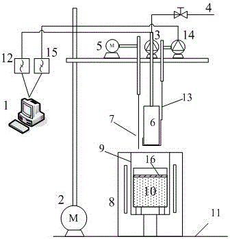
[0020] Such as Figure 1 ~ Figure 4 As shown, an embodiment of the present invention includes a base 11 on which an induction furnace 8, a liquid level positioning bracket 5, a crystallizer copper mold movement system bracket 2, a vibration system motor 3, and a drawing motor 14 are fixed. There is a crucible 9 for holding molten steel 10 and continuous casting mold mold slag 16; above the induction furnace 8, there are liquid level positioning electrodes 7, billet drawing device 13 and mold copper mold 6, and the liquid level positioning electrodes 7 are fixed On the liquid level positioning bracket that can move vertically under the drive of the liquid level positioning motor 5; the crystallizer copper mold 6 is fixed on the crystallizer that can move vertically under the drive of the mold copper mold movement system motor On the support 2 of the copper mold movement system, the vibration system motor 3 can drive the crystallizer copper mold 6 to vibrate according to the set...


PUM

PropertyMeasurementUnit
thicknessaaaaaaaaaa
sizeaaaaaaaaaa

Abstract

The invention discloses a device and method for simulating the crack formation of initially solidified slabs in a continuous casting crystallizer. The steel to be tested is melted in an induction furnace; The mold slag is completely melted, and the temperature of the mold slag and the molten steel are measured to ensure that the temperature of the molten steel remains at the pouring temperature. Insert the copper mold of the simulated crystallizer into the molten pool, and the mold slag is cooled rapidly on the copper mold to form a mold slag film; when a certain length of initially solidified shell is solidified on the copper mold, the copper mold stops moving downward and stays for a few seconds The rear copper mold drives the solidified shell to move upwards out of the molten pool, and the casting device drives the newly solidified initial solidified shell to move downward. The initially solidified billet shell moves downward relative to the copper mold, and the boss on the copper mold will project the initial solidified billet shell, and cracks are generated on the surface of the initially solidified billet shell. The method of the invention can accurately control the generation of cracks on the surface of the initially solidified slab shell under different stress conditions, and measure the stress data in real time with high data accuracy.

Description

technical field [0001] The invention relates to a device and method for simulating the formation of cracks on the surface of the initially solidified slab shell in a continuous casting crystallizer in the steel production process. Background technique [0002] In the continuous casting process, slab surface cracks have been a major problem for domestic and foreign steel mills for a long time. Due to many influencing factors, although a lot of efforts by scientific researchers, most of them can only reduce the occurrence rate, but fail to fundamentally resolved. With the improvement of productivity and the requirement of hot rolling rate increase, slab surface cracks have become an important defect affecting continuous casting production, and more and more attention has been paid to preventing slab surface cracks. [0003] During the cooling process of the slab in the mold, the initially solidified slab shell is most prone to cracks due to the thermal stress generated by the...

Claims


Application Information

Patent Timeline
Patent Type & Authority Patents(China)
IPC IPC(8): G01N3/00
Inventor 王万林马范军吕培生黄道远周乐君
Owner CENT SOUTH UNIV
Why Eureka
Try Eureka