Hot redundancy interlocking subsystem and main and standby switching method thereof

A master-standby switching and subsystem technology, applied in the field of interlocking architecture, can solve problems such as the inability to eliminate software common-mode faults, and achieve the effect of avoiding performance defects and eliminating common-mode faults

Inactive Publication Date: 2015-01-07
SHANGHAI ELECTRIC THALES TRANSPORTATION AUTOMATION SYST CO LTD
View PDF3 Cites 23 Cited by
  • Summary
  • Abstract
  • Description
  • Claims
  • Application Information

AI Technical Summary

Problems solved by technology

Furthermore, the dual-CPU clock synchronization method has the disadvantage of being unable to implement two sets of different algorithms in the two CPUs, and cannot eliminate the common mode fault of the software.

Method used


Image

  • Hot redundancy interlocking subsystem and main and standby switching method thereof
  • Hot redundancy interlocking subsystem and main and standby switching method thereof
  • Hot redundancy interlocking subsystem and main and standby switching method thereof

Examples


Embodiment Construction

[0025] The present invention will be further described below in conjunction with accompanying drawing.

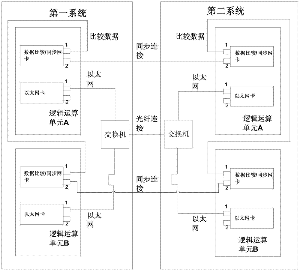
[0026] see figure 1 , the thermal redundancy interlocking subsystem of the present invention includes the same first system and second system,

[0027] The first system and the second system are connected synchronously to compare the I / O status and received information, and perform hot redundancy switching. Both the first system and the second system include a switch, and two CPUs with heterogeneous hardware (ie figure 1 In the logic operation unit A, logic operation unit B). The two CPUs run two sets of different software with differences to realize system synchronization and hot standby switching. In this embodiment, the two CPUs are respectively Intel and Cyrex products, and their running speeds and main frequencies are different, and each unit runs software compiled by different compilers.

[0028] figure 1 , each CPU includes: data comparison / synchronization netwo...


PUM


Abstract

The invention discloses a hot redundancy interlocking subsystem. The hot redundancy interlocking subsystem comprises a first system and a second system which are identical and are connected, wherein each of the first system and the second system comprises two heterogeneous hardware and two CPUs synchronizing at task level. The two sets of different software run on two CPUs respectively. The first system and the second system obtain inputs from track sides and synchronize preset time for one time, and operations of the two systems are compared and then output simultaneously. The hot redundancy interlocking subsystem achieves a hot redundancy double 2-vote-2 hot standby switching mechanism.

Description

technical field [0001] The invention relates to an interlocking architecture applied to a subway CBTC (Communication Based Train Control, communication-based train control) system. Background technique [0002] In the development of the existing CBTC interlocking platform, the interlocking architecture generally adopts a 2 by 2 platform. It is composed of the same 2 out of 2 structure of the two series A and B. Each series of motherboards is equipped with two CPUs (central processing units) with identical hardware, and a set of common software is run inside. Under normal circumstances, one system is the logical master, and the other is the logical backup. The two CPUs of each system adopt clock-level synchronization, and automatically switch to the backup system when the main system fails. However, due to the use of clock-level synchronization, it is directly subject to the main processing frequency of the CPU, that is, the CPU clock frequency cannot be too fast, otherwise ...

Claims


Application Information

Patent Timeline
Patent Type & Authority Applications(China)
IPC IPC(8): G06F11/16
Inventor 朱跃梁孙来平李广诚
Owner SHANGHAI ELECTRIC THALES TRANSPORTATION AUTOMATION SYST CO LTD
Why Eureka
Try Eureka