
An environmental simulation test device and method for a high-energy pipeline rupture accident in a nuclear power plant

A technology for environmental simulation test and high-energy pipeline, which is applied to the environmental simulation test device and field of high-energy pipeline rupture accident in nuclear power plants, can solve the problems of low peak pulling rate, less severe accident conditions for high-energy pipeline rupture, and high peak temperature, and achieves a large volume. Effect

Active Publication Date: 2017-01-11
SHANGHAI POWER EQUIP RES INST
View PDF4 Cites 0 Cited by
  • Summary
  • Abstract
  • Description
  • Claims
  • Application Information

AI Technical Summary

Problems solved by technology

The greatest difficulty of the above test is that at the beginning of the test, steam is sprayed into the test container, and the temperature and pressure in the container rise rapidly. Taking the AP1000 nuclear power plant as an example, the temperature rises from 51°C to 149°C (including 8°C) in the first second. ℃ margin), the pressure rises from 0.122MPa to 0.177MPa. For large equipment, this peak pulling process is particularly difficult
In contrast, the high-energy pipeline rupture accident conditions outside the containment are not so severe, the environmental conditions are at normal pressure, and there is no chemical spraying, and the initial peak pulling rate is also slightly lower. Taking the AP1000 nuclear power plant as an example, No. The temperature rose from 41°C to 157°C within 1.9 seconds (including an 8°C margin), but the peak temperature was higher (up to 250°C or more), and the accident lasted only two weeks
Most of the existing test devices cannot achieve the above-mentioned initial thermal shock process, and only individual laboratory small-scale test containers can achieve it, which can only be used for some small-scale equipment tests, and cannot meet the test requirements of a large number of larger-scale equipment, such as : Nuclear power plant containment electrical penetrations, nuclear valve actuators, etc.

Method used


Image

  • An environmental simulation test device and method for a high-energy pipeline rupture accident in a nuclear power plant

Examples


Embodiment

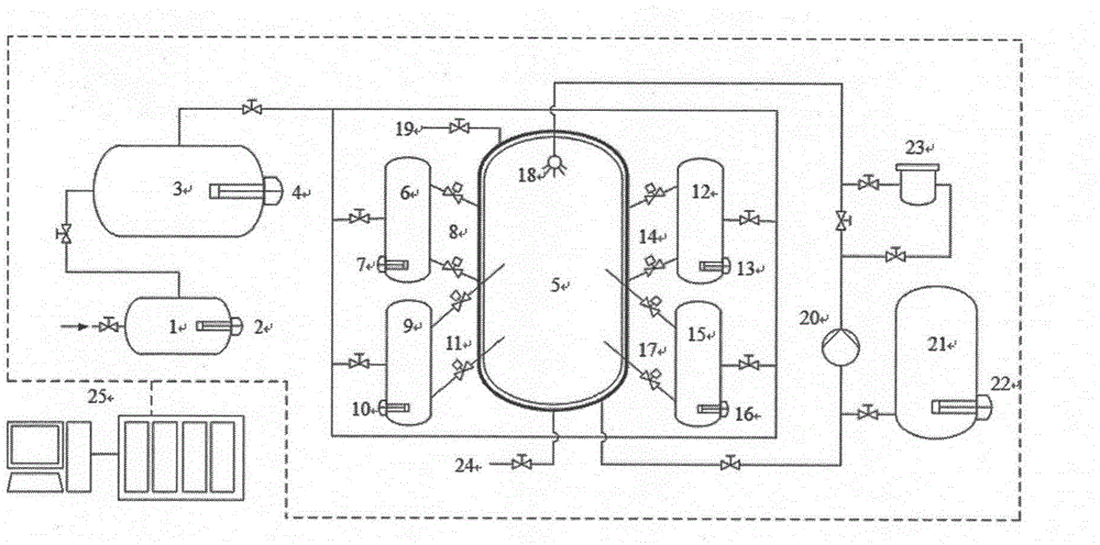
[0028] Such as figure 1 As shown, it is a structural schematic diagram of the environmental simulation test device for high-energy pipeline rupture accidents in nuclear power plants. The high-energy pipeline rupture accident environment simulation test device for nuclear power plants includes a steam generator 1, a gas storage tank 3, a test chamber 5, and a first accumulator 6 , the second accumulator 9, the third accumulator 12, the fourth accumulator 15, a spray system, an automatic control system and a data acquisition system. The steam generator 1 is connected to the steam storage tank 3 through pipelines, and the steam storage tanks 3 are respectively connected to four accumulators through pipelines. The pipeline between the steam generator 1 and the steam storage tank 3 and the gas storage tank 3 and the accumulator There are isolation valves on the pipelines. The accumulator is arranged around the test chamber 5 and its steam outlet is connected to the steam inlet of ...


PUM


Abstract

The invention provides a device and method for carrying out tests for stimulating the environment in a high energy pipeline rupture accident in a nuclear power plant. The device is characterized by comprises a steam generator, the steam generator is connected to a steam storage tank through a pipeline, the steam storage tank is connected to at least one energy storage device through a pipeline, the energy storage device is arranged on the periphery of a testing chamber, the steam outlet of energy storage device is connected to the steam inlet of the testing chamber through a pipeline, a quick open pneumatic valve set is arranged on the pipeline that connects the steam outlet of energy storage device and the steam inlet of the testing chamber, and the testing chamber is connected to a spraying system. The provided device can stimulate the primary heat impact environmental conditions in a most severe high energy pipe rupture accident in an AP / CAP series III generation nuclear power plant.

Description

technical field [0001] The invention relates to a device and method for simulating a high-energy pipeline rupture accident environment in a nuclear power plant. Design basis accident environment qualification for safety equipment to verify the functional operability of equipment under accident environment conditions. Background technique [0002] my country pursues the principle of efficiently developing nuclear power on the basis of ensuring safety. The passive safety advanced pressurized water reactor nuclear power technology (AP / CAP series) will be one of the main reactor types for future nuclear power construction in my country due to its inherent safety characteristics, including from Westinghouse Corporation of the United States introduced AP1000 nuclear power technology, CAP1000 nuclear power technology digested and absorbed by my country, and CAP1400 nuclear power technology with completely independent intellectual property rights. AP / CAP series nuclear power plants ...

Claims


Application Information

Patent Timeline
Patent Type & Authority Patents(China)
IPC IPC(8): G21C17/017
CPCG21C17/017Y02E30/30
Inventor 黄志强张国坤陈功名葛磊尚恒郑开云陈智
Owner SHANGHAI POWER EQUIP RES INST
Learn More