Continuous electroplating device

An electroplating device and electroplating solution technology, applied in the direction of the plating tank, etc., can solve the problems of low electroplating efficiency, difficulty in applying high current, etc., achieve high electroplating efficiency, reduce the overall equipment size, and maximize the effect of space efficiency

Inactive Publication Date: 2016-12-14
INKTEC CO LTD
View PDF24 Cites 0 Cited by
  • Summary
  • Abstract
  • Description
  • Claims
  • Application Information

AI Technical Summary

Problems solved by technology

[0004] In addition, since it is difficult to apply a high current according to conventional techniques, electroplating is performed by applying a relatively low current for a long period of time, resulting in inefficient plating

Method used


Image

  • Continuous electroplating device
  • Continuous electroplating device
  • Continuous electroplating device

Examples


Embodiment Construction

[0021] Hereinafter, the present invention will be described in detail with reference to the accompanying drawings.

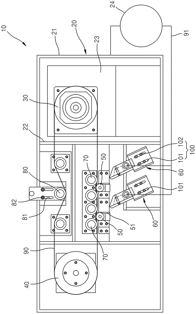
[0022] The continuous electroplating device 10 according to an embodiment of the present invention forms a predetermined electroplating layer on the surface of the electroplating target 90, wherein the electroplating target 90 has a predetermined width and extends in a predetermined direction; the continuous electroplating device 10 can be continuously formed on the surface of the electroplating target 90 Plating. Specifically, the continuous plating apparatus 10 uses a printing method to form a plating layer on a plating target 90 (elastic substrate or rigid substrate).

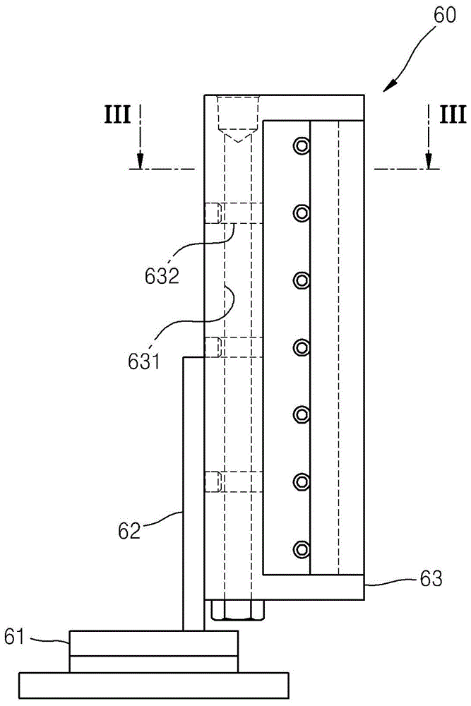
[0023] The continuous plating apparatus 10 includes a frame 20 , a driving roll 30 , a driven roll 40 , a negative roll 50 , a positive nozzle unit 60 , a tension maintaining roll 70 and a tension supply roll 80 .

[0024] The frame 20 is the main body of the continuous electroplating device ...


PUM


Abstract

The present invention relates to a continuous electroplating apparatus, and more particularly, to such a continuous electroplating apparatus comprising: a frame; a driving roller on which an object to be electroplated having a predetermined width and extending in one direction is wound, wherein, The driving roller is rotated by the power transmitted by the rotating device, and the driving roller is installed in the frame; the driven roller, which is installed in the frame and separated from the driving roller so that the material to be electroplated is caught on the driven roller target; a negative electrode roller installed in the frame and arranged between the driving roller and the driven roller along the moving path of the target to be electroplated, wherein the negative electrode roller contacts the target to be electroplated so as to negatively charge the target to be electroplated; and The positive electrode nozzle unit is installed in the frame and sprays the plating solution including positive ions onto the contact area between the negative electrode roll and the target to be plated.

Description

technical field [0001] The present invention relates to a continuous plating device, and more particularly, to a continuous plating device capable of forming a plating layer by spraying a plating solution only to a target plating portion. Background technique [0002] Usually thin products such as printed circuit boards (PCBs) are plated by using a horizontal plating method of continuously plating a plating target. The electroplating method is performed using an electroplating apparatus including: an electroplating tank storing an electroplating solution, the electroplating tank including an inlet and an outlet through which an electroplating target is input and output, respectively; a non-soluble positive electrode; The target is conveyed in the horizontal direction to pass through the plating tank; and negative rollers are provided in front of the plating tank to negatively charge the plating target; in addition, guide rollers are included at the entrance and exit of the p...

Claims


Application Information

Patent Timeline
Patent Type & Authority Patents(China)
IPC IPC(8): C25D17/02
CPCC25D17/02C25D7/0628C25D7/0642C25D7/0657C25D7/0685
Inventor 郑光春庾明凤韩英求温雄龟
Owner INKTEC CO LTD
Why Eureka
Try Eureka