
System and method for synchronized triggering of test equipment for testing mimo transceivers

A signal test and trigger signal technology, applied in the direction of instrument, transmission system, electronic circuit test, etc.

Active Publication Date: 2015-01-07
LITEPOINT
View PDF5 Cites 6 Cited by
  • Summary
  • Abstract
  • Description
  • Claims
  • Application Information

AI Technical Summary

Problems solved by technology

For example, each tester must be able to trigger other testers, since the DUT may not use all the transmitters available

Method used


Image

  • System and method for synchronized triggering of test equipment for testing mimo transceivers
  • System and method for synchronized triggering of test equipment for testing mimo transceivers

Examples


Embodiment Construction

[0011] The invention will now be described with reference to the accompanying drawings, in which like reference numerals indicate like elements. The following detailed description is an exemplary embodiment of the claimed invention taken in conjunction with the accompanying drawings. Such descriptions are intended to be illustrative, not limiting, with respect to the scope of the invention. Such embodiments are described in detail to enable those of ordinary skill in the art to practice the subject invention, and it is to be understood that other embodiments may be practiced with some changes without departing from the spirit or scope of the subject invention. .

[0012] Throughout the present invention, unless the context clearly indicates otherwise, it should be understood that the term "signal" may refer to one or more currents, one or more voltages or data signals.

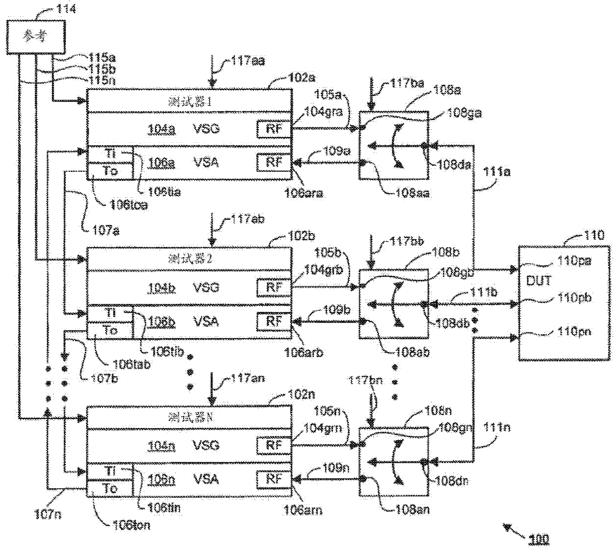
[0013] see figure 1 , the system 100 for testing a plurality of MIMO devices using a plurality of RF sig...


PUM


Abstract

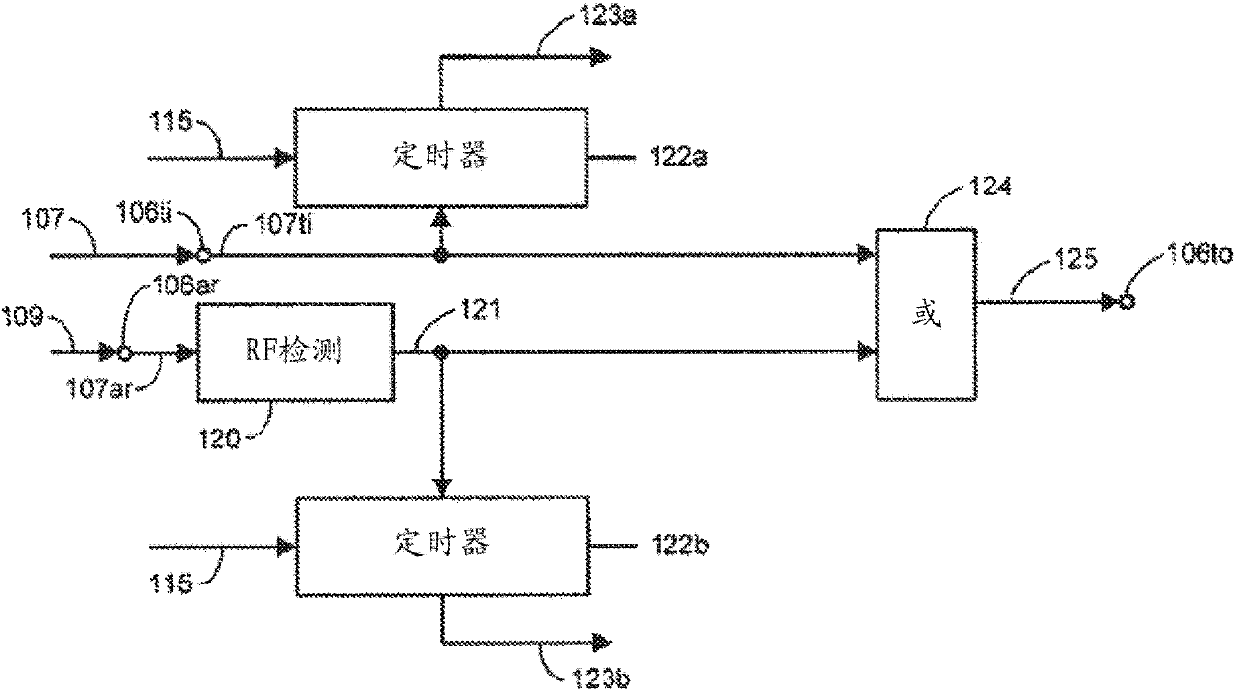
A system and method for testing multiple-input-multiple-output (MIMO) devices under test (DUTs) with multiple radio frequency (RF) signal testers. Each tester receives one or more RF signals from one or more of the DUTs, and the testers are mutually coupled in a ring such that successive ones receive a trigger input signal from an upstream tester and provide a trigger output signal to a downstream tester. Each tester is responsive to its input trigger signal and its one or more RF signals by providing its output trigger signal such that its output trigger signal has an asserted state initiated in response to an assertion of its input trigger signal and a transcending of a predetermined magnitude by at least one of the one or more RF signals.

Description

technical field [0001] The present invention generally relates to systems and methods for testing electronic instruments. More particularly, the present invention relates to improvements to systems and methods for testing wireless signal transceivers using test platforms consisting of hardware, firmware and / or software components. Background technique [0002] Many of today's handheld devices use wireless "connections" for telephony, digital data transfer, geolocation, and more. Despite differences in spectral range, modulation method, and power spectral density, wireless connectivity standards transmit and receive data in isochronous packets. In general, all of these wireless functions are defined by industry-accepted standards, such as IEEE802.11 and 3GPP LTE, which specify the parameters and limits that devices with the above functions must comply with. [0003] At any point in the continuous process of device development, it may be necessary to test and verify that the...

Claims


Application Information

Patent Timeline
Patent Type & Authority Applications(China)
IPC IPC(8): G01R29/08G01R31/317G06K17/00
CPCH04B7/0413H04B17/0085
Inventor 克里斯蒂安·沃尔夫·厄尔高王瑞祖约翰·克里斯托弗·鲁卡兹石广
Owner LITEPOINT
Learn More