Injection mould provided with hydraulic motor thread return mechanism protection device

A technology of hydraulic motor and protection device, applied in the field of injection molds, can solve the problems of frequent mold repairs, shortened use time of parts, threaded cores, threaded sleeve bearings, etc. The effect of prolonging the overall life and ensuring the service life

Active Publication Date: 2015-01-14
和动力智能科技(东莞)有限公司
View PDF5 Cites 1 Cited by
  • Summary
  • Abstract
  • Description
  • Claims
  • Application Information

AI Technical Summary

Problems solved by technology

[0005] 3. When the hydraulic motor continues to work next time, the threaded core may be killed, causing the motor to stop turning;
[0006] 4. Excessive friction between the upper end of the threaded core and the core of the mold, resulting in flashing of the product
[0007] 5. Forced stop, gears, threaded cores, threaded sleeves and bearings will be damaged and cracked, resulting in shortened service life of parts, frequent mold repairs, affecting production and affecting the overall life of the mold
[0008] The above consequences must be solved by repairing molds and replacing parts, which has brought a great impact on production and caused the manufacturer to pay a lot of mold repair costs.

Method used


Image

  • Injection mould provided with hydraulic motor thread return mechanism protection device
  • Injection mould provided with hydraulic motor thread return mechanism protection device
  • Injection mould provided with hydraulic motor thread return mechanism protection device

Examples


Embodiment Construction

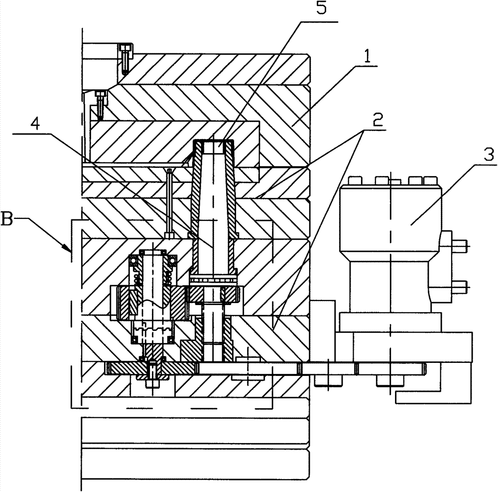
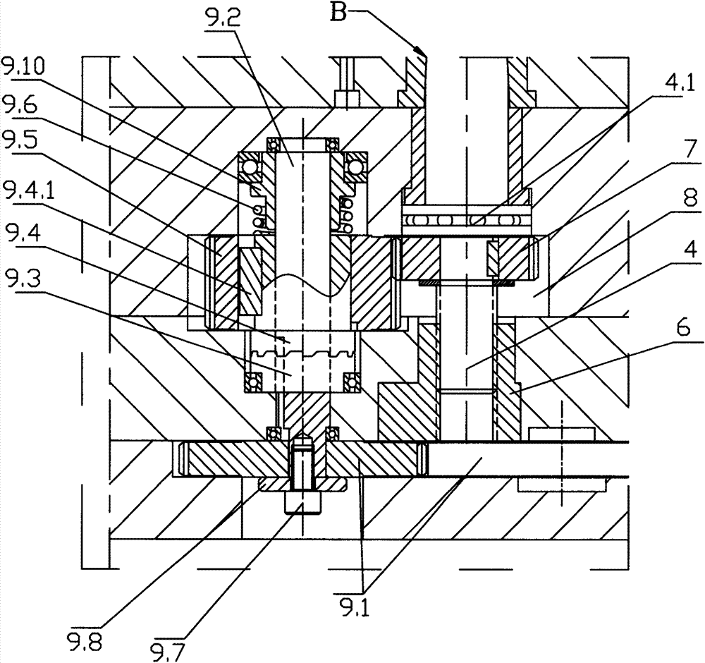
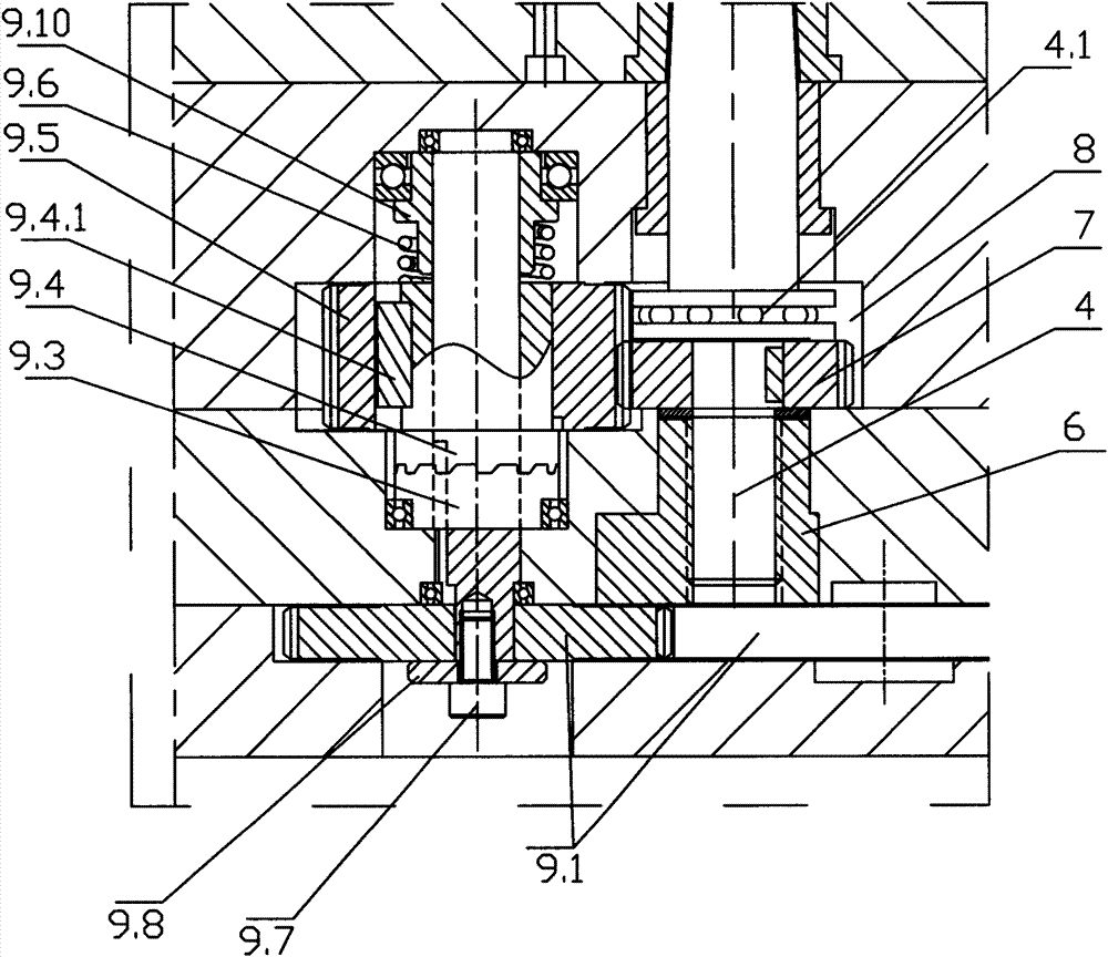
[0037] refer to Figure 1-Figure 6 As shown, an injection mold with a protection device for a hydraulic motor thread withdrawal mechanism includes an upper mold 1, a lower mold 2, a power assembly 3 and a threaded core 4 for forming product threads, and the upper mold 1 and the lower mold 2 are bonded together. The product molding cavity 5 is formed, which also includes a transmission assembly with a power transmission protection function. The threaded core 4 is located in the lower mold 2 and the upper end is located in the product forming cavity 5. The lower end of the threaded core 4 is matched with a convenient screw thread for guiding. The threaded sleeve 6 for the axial movement of the core 4, the threaded sleeve 6 is fixed in the lower mold 2; the driven gear 7 is fixed on the threaded core 4, and the driven gear 7 is located in the lower mold 2 and moves axially with the threaded core 4. In the stroke limiting cavity 8 of the mold 2, the driven gear 7 moves up and down...


PUM


Abstract

The invention relates to an injection mould provided with a hydraulic motor thread return mechanism protection device. The injection mould comprises an upper mould, a lower mould, a power component, a thread mold core for molding product threads, and a transmitting assembly, wherein the lower end of the thread mold core is provided with a thread bushing having a guide function in a matching way, and the thread mold core can conveniently move along the axial direction through the thread bushing; the thread bushing is fixed in the lower mould; a driven gear is fixed on the thread mold core, and linkage is realized between the driven gear and the power component by the transmitting assembly; when the mould is opened and closed, and the thread mold core reaches one of two limiting positions of the upper end and the lower end in the power transfer process, large resistance is applied to the transmitting assembly, and an upper rotating sleeve and a lower rotating sleeve which are arranged on the transmitting assembly slip and get away from the transmitting assembly, so that power is cut off in time, all the parts are prevented from being damaged or broken by vibration, the thread mold core is prevented from being very tight with a mold kernel or the thread bushing when moving up and down, the service life of the mould is effectively guaranteed, and the maintenance cost is lowered. The injection mould belongs to the technical field of mould equipment.

Description

technical field [0001] The invention belongs to the technical field of mold equipment, and in particular relates to an injection mold equipped with a protective device for an oil pressure motor screw-removing mechanism. Background technique [0002] Injection mold is a kind of mold, and its application is very common, especially in the production of some plastic products. At present, some of the molds used to produce threaded products use hydraulic motors as power components, which are used to unscrew the power during mold ejection and clamping. And the screw-in limit is often the biggest difficulty. The motor has no brake device and is driven entirely by oil pressure. When the oil pressure is turned off, the motor will continue to rotate under the effect of oil pressure drop. parts) the upper and lower two thrust bearings are forcibly stopped. There are following disadvantages: [0003] 1. When closing the mold, it is easy to make the upper end of the threaded core and t...

Claims


Application Information

Patent Timeline
Patent Type & Authority Applications(China)
IPC IPC(8): B29C45/26B29C45/84
CPCB29C45/262B29C45/332B29C45/84
Inventor 章琴琴
Owner 和动力智能科技(东莞)有限公司
Why Eureka
Try Eureka