
Dynamic spring lead-out piece for small relay

A technology of lead-out sheet and relay, applied in relays, electromagnetic relays, electromagnetic relay details and other directions, can solve the problems of inconvenient assembly and use, lack of limit structure, etc., to achieve the effect of convenient assembly and use, and avoid the effect of left and right lateral sliding

Inactive Publication Date: 2015-01-14
NINGBO TIANBO GANGLIAN ELECTRONICS
View PDF0 Cites 0 Cited by
  • Summary
  • Abstract
  • Description
  • Claims
  • Application Information

AI Technical Summary

Problems solved by technology

[0005] 2. Since the other side of the first bending plate lacks a limiting structure with the shell, after installation, it slides left and right horizontally, which brings inconvenience to actual assembly and use

Method used


Image

  • Dynamic spring lead-out piece for small relay

Examples


Embodiment Construction

[0017] The present invention will be further described below in conjunction with the accompanying drawings and specific embodiments.

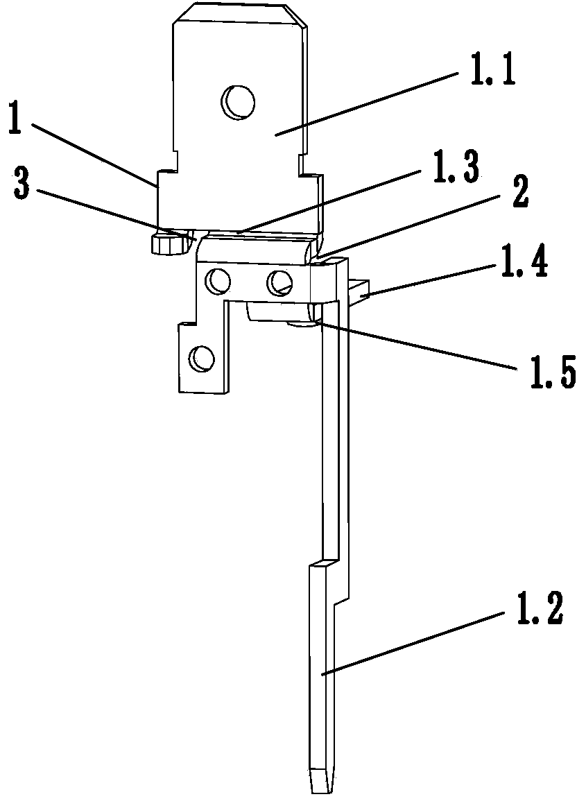
[0018] Such as figure 1 As shown, the small relay moving spring lead-out piece of the present invention includes a moving spring lead-out piece body 1, one end of the moving spring lead-out piece body 1 is provided with a connecting pin 1.1 connected to a quick connector and a wiring hole, the moving spring The other end of the spring lead-out sheet body 1 is provided with a pin 1.2 welded to the circuit board, and the bottom of the terminal pin 1.1 is provided with a first bending plate 1.3, and the pin 1.2 is located on the side of the first bending plate 1.3 , the middle part of the moving spring lead-out piece body 1 is provided with a curved second bending plate 1.4, and a first gap 2 is provided between the top of the pin 1.2 and the side wall of the first bending plate 1.3, and the pin is bent During the process, avoid its edge from pre...


PUM


Abstract

The invention discloses a dynamic spring lead-out piece for a small relay. The dynamic spring lead-out piece includes a dynamic spring lead-out piece body (1). A wiring pin (1.1) is arranged at one end of the dynamic spring lead-out piece body (1). A base pin (1.2) is arranged at the other end of the dynamic spring lead-out piece body (1). A first bent plate (1.3) is arranged at the bottom of the wiring pin (1.1). The base pin (1.2) is located on the side face of the first bent plate (1.3). A second bent plate (1.4) is arranged in the middle of the dynamic spring lead-out piece body (1). A first notch (2) is formed between the top end of the base pin (1.2) and the side wall of the first bent plate (1.3). A second notch (3) used for positioning relative to an outer shell is formed in the part, close to the side wall, of the other side of the first bent plate (1.3). According to the dynamic spring lead-out piece for the small relay, the base pin can be well bent to meet a required angle, and the effect of limiting between the first bent plate and the outer shell is good.

Description

technical field [0001] The invention relates to an electronic control device, in particular to a small relay movable spring lead-out piece. Background technique [0002] When the relay is working, as long as a certain voltage is applied to both ends of the coil, a certain current will flow through the coil, thereby generating an electromagnetic effect. The armature pushes the moving spring through the push rod until the moving spring and the static spring are attracted. When the coil is powered off, the electromagnetic attraction force disappears, the armature returns to its original position, and the moving spring is separated from the static spring. [0003] At present, the moving spring lead-out piece of a small relay includes a moving spring lead-out piece body, one end of the moving spring lead-out piece body is provided with a connecting pin connected to a quick connector and a wiring hole, and the other end of the moving spring lead-out piece body is There are pins w...

Claims


Application Information

Patent Timeline
IPC IPC(8): H01H50/64H01H50/14
CPCH01H50/646H01H50/14
Inventor 王铁伟王坚敏
Owner NINGBO TIANBO GANGLIAN ELECTRONICS
Learn More