
Stamping mold for metal fittings

A technology for stamping dies and metal accessories, applied in metal processing equipment, forming tools, manufacturing tools, etc., can solve the problems of increasing the probability of defective products and affecting the service life of templates, achieving good heat dissipation effect, accelerating heat dissipation, Avoid massive stacking effects

Inactive Publication Date: 2020-12-11
程亮
View PDF7 Cites 0 Cited by
  • Summary
  • Abstract
  • Description
  • Claims
  • Application Information

AI Technical Summary

Problems solved by technology

[0006] The purpose of the present invention is to provide a stamping die for metal fittings to solve the problem of heat dissipation in the stamping dies for metal fittings proposed in the above background technology. During the stamping process of the device, the template will generate a certain amount of heat. The time is in a state of high temperature, which is likely to affect the service life of the template. At the same time, there are still some shortcomings in the position limitation of the metal parts stamping die for the processing material. If the processing material cannot be limited, it is easy to cause the material to slide during processing The problem of increased probability of defective products

Method used

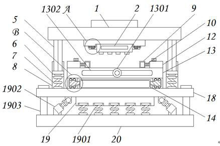
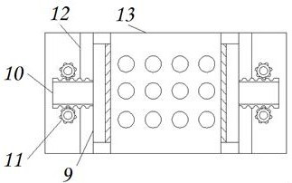
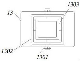

Image

  • Stamping mold for metal fittings
  • Stamping mold for metal fittings
  • Stamping mold for metal fittings

Examples


Embodiment Construction

[0029] The following will clearly and completely describe the technical solutions in the embodiments of the present invention with reference to the accompanying drawings in the embodiments of the present invention. Obviously, the described embodiments are only some, not all, embodiments of the present invention. Based on the embodiments of the present invention, all other embodiments obtained by persons of ordinary skill in the art without making creative efforts belong to the protection scope of the present invention.

[0030] see Figure 1-8 , the present invention provides a technical solution: a stamping die for metal accessories, including a connecting plate 1, a stamping device 2, a first connecting block 3, a locking rod 4, a lifting column 5, a lifting block 6, a first spring 7, a hollow Column 8, limit plate 9, second connecting block 10, transmission block 11, hollow block 12, template 13, water inlet 1301, outer ring pipe 1302, inner ring pipe 1303, push plate 14, t...


PUM


Abstract

The invention discloses a stamping mold for metal fittings. The stamping mold comprises a connecting plate, a limiting plate and a pushing plate, wherein the bottom end of the connecting plate is connected to a stamping device; the two ends of the stamping device are fixedly provided with first connecting blocks; locking rods are connected inside the first connecting blocks; sides of the locking rods are fixedly provided with lifting columns; the bottom ends of the lifting columns are equipped with lifting blocks; bottom ends of the lifting blocks are connected to first springs; outer sides ofthe first springs are fixedly provided with hollow columns; the limiting plate is arranged on the bottom of the connecting plate, and one end of the limiting plate is connected to a second connectingblock; the two ends of the second connecting block are equipped with transmission blocks; outer sides of the transmission blocks are fixedly equipped with hollow blocks; and bottom ends of the hollowblocks are connected to a molding board. The stamping mold for the metal fittings disclosed by the invention is provided with a device for limiting processing material and a structure for automatically pushing out finished products, has relatively good heat dissipation effect and damping buffer effect, and is convenient to mount, regulate and use by a user.

Description

technical field [0001] The invention relates to the technical field of metal stamping, in particular to a metal accessory stamping die. Background technique [0002] Stamping die is a special process equipment for processing metal materials into parts or semi-finished products. When stamping, it uses pressure to separate or plastically deform metal materials to obtain the required parts. Compared with traditional castings and forgings , Stamping parts have the characteristics of thinness, lightness and uniformity. At the same time, stamping can produce ribbed, undulating or flanging workpieces that are difficult to manufacture by other methods, thereby improving the rigidity of the processed parts. The mold used for stamping is called a stamping die. There are still some deficiencies in the stamping dies on the market, such as: [0003] 1. The traditional stamping dies for metal parts still have certain deficiencies in heat dissipation. During the stamping process of the de...

Claims


Application Information

Patent Timeline
Patent Type & Authority Applications(China)
IPC IPC(8): B21D37/10B21D43/00B21D37/16B21D45/02
CPCB21D37/10B21D43/003B21D37/16B21D45/02
Inventor 不公告发明人
Owner 程亮
Learn More