Stamping die control method

A control method and technology for stamping dies, applied in the field of stamping dies, can solve the problems of difficult die manufacturing, complicated parts processing technology, and inability to set a wedge structure.

Active Publication Date: 2015-01-21
东莞市盈德精密五金有限公司
View PDF7 Cites 8 Cited by
  • Summary
  • Abstract
  • Description
  • Claims
  • Application Information

AI Technical Summary

Problems solved by technology

(2) The oblique wedge structure in the existing side shaping mechanism is set inside the stamping die, but the internal space of the stamping die is l

Method used


Image

  • Stamping die control method
  • Stamping die control method
  • Stamping die control method

Examples


Embodiment Construction

[0050] Combine below Figure 1 to Figure 7 , the present invention is further described:

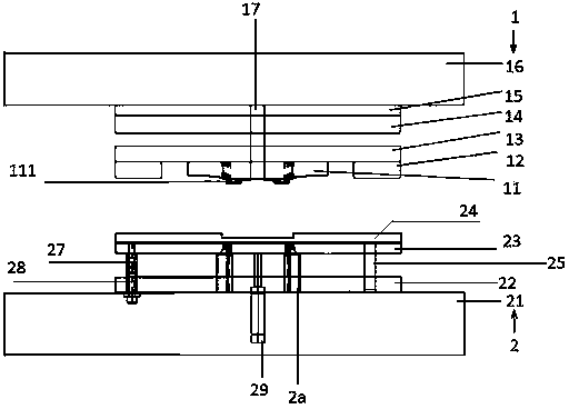
[0051] Such as figure 1 As shown, the first flanging die in the stamping die of the present invention is composed of an upper die 1 and a lower die 2 , and an upper die punch 11 is fixed on the upper die 1 .

[0052] The structure of the lower die 2 is as follows: the lower base 21 is fixed with a lower backing plate 22, the lower clamping plate 23 and the upper backing plate 24 are fixed together by screws, the base of the nitrogen spring 29 is fixed on the lower die base 21, and the piston of the nitrogen spring 29 The rod top is on the lower clamping plate 23, the right inserting column 25 and the left inserting column 27 are all fixed on the lower mold base 21, the lower backing plate 22, the lower splint 23 and the upper backing plate 24 are all inserted on the right inserting post 25 and the left inserting post 27 , a spring 28 is inserted into the left post 27, the lower end of ...


PUM


Abstract

The invention relates to a stamping die control method. The lower end of a locating rod (39) is sleeved with a compression spring (391), the upper end of the compression spring (391) is connected with a T-shaped supporting plate (392), a through hole is formed in the vertical portion of the T-shaped supporting plate (392), the locating rod (39) penetrates through the through hole, and the horizontal portion of the T-shaped supporting plate (392) is used for supporting a stamping part; columnar storing grooves (394) are formed in the upper end of the locating rod (39) in the axial direction, the upper ends or the lower ends of the storing grooves (394) are connected with connecting shafts (395), the two ends of each connecting shaft (395) are fixed on the walls of the storing grooves (394), elastic stop rods (393) are connected with the connecting shafts (395) and are rotatable, and the included angle between each elastic stop rod (393) and the locating rod (39) changes within 0-90 degrees. A stamping part pressing and limiting mechanism has a discharging function, arrangement space in a die is saved, and stamping efficiency is improved.

Description

technical field [0001] The invention relates to a stamping die, in particular to a stamping die control method. Background technique [0002] There is still no tool in the existing market that realizes the three functions of pressing, limiting and unloading stamping parts in one. Therefore, too many components will lead to waste of space in the mold and reduce stamping efficiency. [0003] Chinese patent: The flanging die of the continuous stamping die of the automobile safety belt hanger, the application publication number CN102012663A discloses a flanging die on the stamping die. Easy to unmold. [0004] However, since the flanging die of the continuous stamping die of the automobile seat belt hanger adopts both horizontal stamping and vertical stamping pressures, in order to ensure the stamping quality of the stamping parts, the stamping parts must be positioned and pressed on the lower die at the same time. Otherwise, it is prone to accuracy deviation. [0005] In ad...

Claims


Application Information

Patent Timeline
IPC IPC(8): B21D19/00B21D37/10B21D43/00B21D45/08
Inventor 王娟姚和中
Owner 东莞市盈德精密五金有限公司
Why Eureka
Try Eureka