Eureka AIR delivers breakthrough ideas for toughest innovation challenges, trusted by R&D personnel around the world.

Automatic multi-wire feeder

A wire feeder and wire feeding technology, which is applied in the field of multi-wire automatic wire feeders, can solve the problems of large footprint, power consumption, and unstable size, etc.

Active Publication Date: 2015-01-21
江苏融威实业有限公司
View PDF6 Cites 9 Cited by
  • Summary
  • Abstract
  • Description
  • Claims
  • Application Information

AI Technical Summary

Problems solved by technology

[0002] All kinds of wires can be supplied to many different types of machines and devices. These machines and devices are used for cutting and smelting of wires. In this process, the problem of wire harness transportation will be involved. The existing wire feeding devices generally pass the wire bundles through Through a movable wheel, the up and down movement of the movable wheel can control the rotation and stop of the pay-off reel. When the wire harness is consumed, the movable wheel moves upwards under the tension of the wire harness, and controls the pay-off device to release the wire harness, and then the movable wheel descends, controlling the pay-off device to stop paying off. , the wire harness continues to move upwards after being consumed, so as to reciprocate the length of the wire feeding. In this process, the wire harness is subjected to a large and inconstant pulling force due to the gravity of the movable wheel, which will cause the wire harness to slip at the wire inlet end. As a result, the cutting length of the wire harness processing equipment is unstable when it is working. In addition, when processing multiple wire harnesses at the same time, it is necessary to run multiple wire feeding devices, which takes up a large area, is cumbersome to operate, and consumes more electricity.

Method used


Image

  • Automatic multi-wire feeder
  • Automatic multi-wire feeder
  • Automatic multi-wire feeder

Examples


Embodiment Construction

[0018] The specific implementation manners of the present invention will be further described in detail below in conjunction with the accompanying drawings and embodiments. The following examples are used to illustrate the present invention, but are not intended to limit the scope of the present invention.

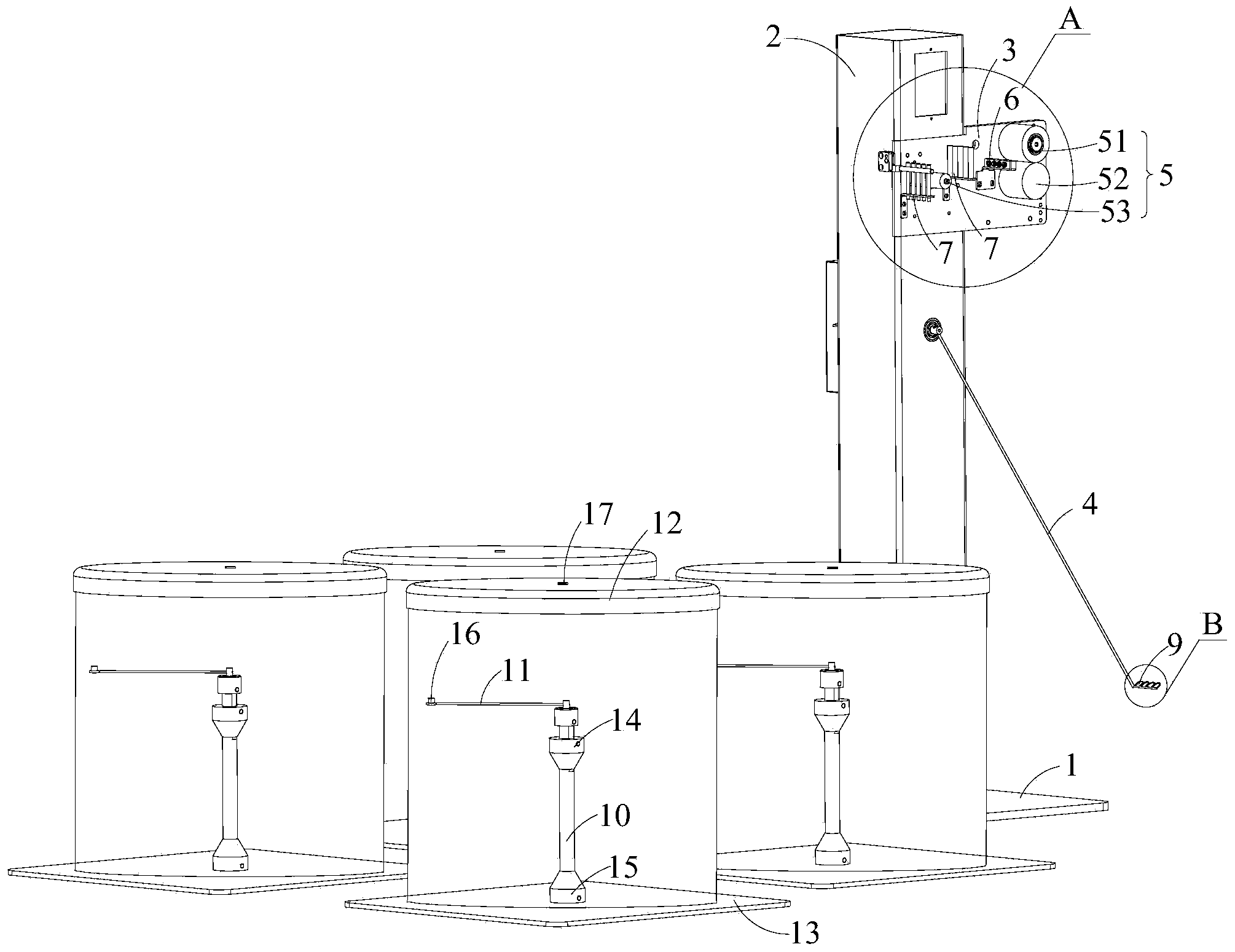
[0019] see Figures 1 to 4 As shown, a multi-wire automatic wire feeder according to a preferred embodiment of the present invention includes a conveying system and a wire pay-off system arranged on one side of the conveying system.

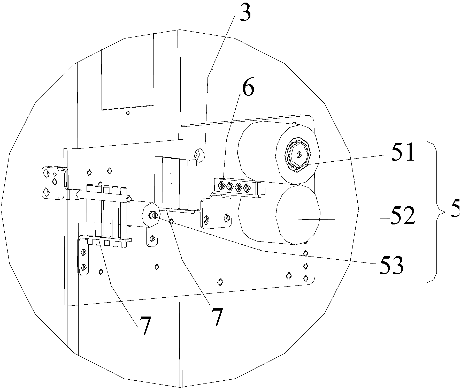
[0020] The conveying system is arranged on the base 1 and includes a first column 2, a square fixed plate 3 fixed on the first column 2, a delivery detection swing arm 4 arranged on the first column 2 and below the fixed plate 3, and a The photoelectric detection sensor (not shown) used to detect the swing position of the delivery detection swing arm 4 on the first column 2, the photoelectric detection sensor model used in this embodiment is...


PUM


Abstract

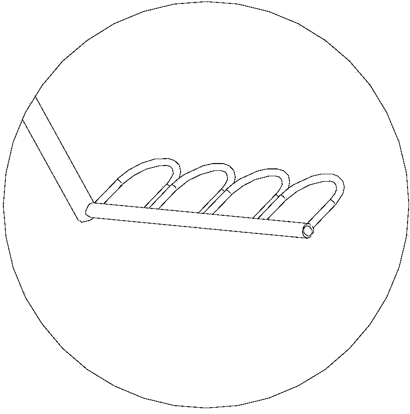
The invention relates to an automatic multi-wire feeder, which comprises a delivery system and a pay-off system, wherein the delivery system comprises a first upright post, a horizontal wire feeding roller group arranged on the first upright post, a first wire passing hole group arranged on one side of the horizontal wire feeding roller group, a delivery motor for driving the horizontal wire feeding roller group, a delivery detection oscillating arm arranged on the first upright post and a photoelectric detection sensor for detecting the oscillating position of the delivery detection oscillating arm to control the delivery motor to be started according to the position of the delivery detection oscillating arm; a second wire passing hole group is arranged at the free end of the delivery detection oscillating arm; the pay-off system comprises at least two pay-off devices; each pay-off device comprises a fixed shaft, a pay-off drum arranged on the fixed shaft in a sleeving way, a pay-off rod movably fixed at the top end of the fixed shaft and perpendicular to the fixed shaft and a sleeve arranged outside the fixed shaft and the pay-off rod in a covering way; threading holes are formed in the free ends of the pay-off rods; central axes of the sleeves are overlapped with those of the fixed shafts; wire outlets are formed in the central positions of the upper surfaces of the sleeves.

Description

technical field [0001] The invention belongs to the technical field of wire harness processing, in particular to a multi-wire automatic wire feeder. Background technique [0002] All kinds of wires can be supplied to many different types of machines and devices. These machines and devices are used for cutting and smelting of wires. In this process, the problem of wire harness transportation will be involved. The existing wire feeding devices generally pass the wire bundles through Through a movable wheel, the up and down movement of the movable wheel can control the rotation and stop of the pay-off reel. When the wire harness is consumed, the movable wheel moves upwards under the tension of the wire harness, and controls the pay-off device to release the wire harness, and then the movable wheel descends, controlling the pay-off device to stop paying off. , the wire harness continues to move upwards after being consumed, so as to reciprocate the length of the wire feeding. In...

Claims


Application Information

Patent Timeline
IPC IPC(8): B65H51/08B65H51/28B65H49/30
Inventor 张金斌
Owner 江苏融威实业有限公司
Why Eureka
Eureka Blog
Learn More