Tunnel excavation three-dimensional model experiment loading device

A technology of loading device and three-dimensional model, which is applied to measurement devices, instruments, scientific instruments, etc., can solve the problems of difficult simulation of tunnel section excavation sequence and support methods, complicated loading process, and unsatisfactory experimental results, and achieves restraint ability. Strong, high experimental efficiency and economic benefits, the effect of high stiffness

Inactive Publication Date: 2015-01-21
ZHEJIANG UNIVERSITY OF SCIENCE AND TECHNOLOGY +1
View PDF4 Cites 16 Cited by
  • Summary
  • Abstract
  • Description
  • Claims
  • Application Information

AI Technical Summary

Problems solved by technology

Among them, the 3D method requires a very large experimental site and equipment, and the loading process is very complicated. In theory, this experimental method is in good agreement with the actual engineering situation, but it is difficult to achieve this effect in the actual operation process, especially under the conditions of a large-scale 3D model Under these conditions, the excavation sequence and support methods of the tunnel section are difficult to simulate, and the experimental results are often unsatisfactory; the 2D method is a simplified experimental method based on a certain theoretical basis. During use, its section is a plane strain problem under the three-dimensional ground stress condition, which has no direct relationship with the actual length of the tunnel. Therefore, as long as the actual three-dimensional ground stress field conditions can be simulated, the two-dimensional tunnel section model can be used instead of the three-dimensional The tunnel model is an efficient and economical experimental method for excavation method simulation and support method simulation

Method used


Image

  • Tunnel excavation three-dimensional model experiment loading device
  • Tunnel excavation three-dimensional model experiment loading device
  • Tunnel excavation three-dimensional model experiment loading device

Examples


Embodiment Construction

[0025] The present invention will be further described below in conjunction with the accompanying drawings and specific embodiments, but the protection scope of the present invention is not limited thereto.

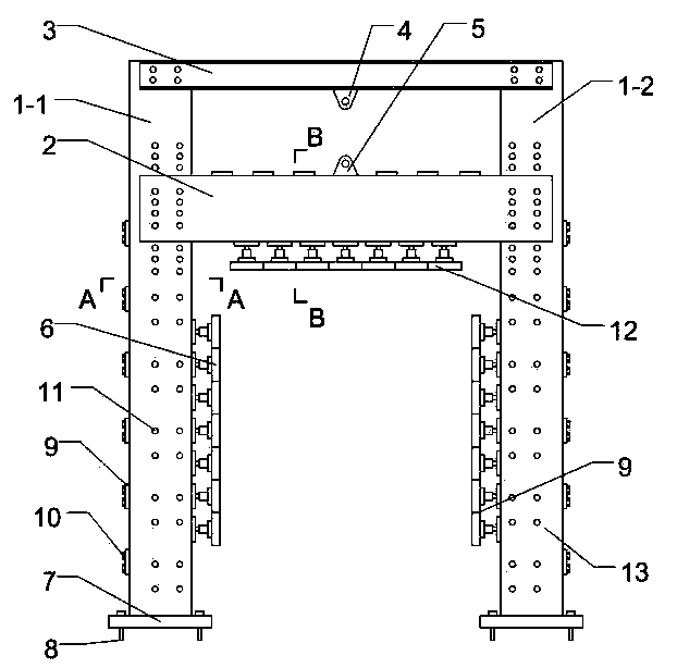
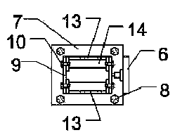
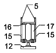
[0026] refer to Figure 1-8 , a loading device for tunnel excavation three-dimensional model experiments, comprising a loading frame, a front baffle at the front of the loading frame, and a rear baffle at the back of the loading frame, the loading frame includes a frame column, a moving beam 2 and an upper beam 3 , the moving crossbeam 2 and the upper crossbeam 3 are respectively perpendicular to the frame column, and the frame column includes a vertically arranged first frame column 1-1 and a second frame column 1-2, and the first frame column 1-1 and the second frame column A number of lateral hydraulic cylinders 6 are symmetrically installed on the inner surface of the column 1-2, and the bottoms of the first frame column 1-1 and the second frame column 1-2 are respect...


PUM


Abstract

The invention relates to a tunnel excavation three-dimensional model experiment loading device. The device comprises a loading frame, a front baffle, a rear baffle and self-balancing reaction frames, wherein the loading frame comprises frame columns, a moving cross beam and an upper cross beam; a plurality of lateral hydraulic cylinders are symmetrically installed on the inner sides of the frame columns; a plurality of vertical hydraulic cylinders are installed at the bottom of the moving cross beam; a lifting device is installed on the upper cross beam; the front baffle comprises a transparent organic glass baffle and a steel channel baffle; a hole is cut in the organic glass baffle; the organic glass baffle is arranged on the inner side of the steel channel baffle; more than one self-balancing reaction frame is arranged outside each of the front and rear baffles respectively; a plurality of jacks are arranged between the self-balancing reaction frames and the front baffle; and jack base plates are arranged on the front baffle. The device can generate various rock and soil mass three-dimensional stress fields with different burial depths and geological conditions and can achieve the chamber excavation model experiments under complicated conditions, such as different clear distances, different sections, and the like under high and low unsymmetrical pressure conditions.

Description

technical field [0001] The invention belongs to the field of railway and highway tunnels, and in particular relates to a loading device for a tunnel excavation three-dimensional model experiment. Background technique [0002] With the rapid development of infrastructure construction such as railways and highways, more and more railways and highways need to pass through mountains and rivers and lakes in the form of tunnels. Due to the constraints of various construction sites, various types of tunnels have emerged. Tunnels, such as small-diameter tunnels, double-arch tunnels, and cross tunnels, etc., and due to various geological conditions, the working environment of the tunnels also has different changes, such as large and small bias tunnels, etc. What should be used under different conditions? Such excavation method has attracted the attention of the engineering community. Different tunnel excavation methods will not only directly affect the stability of the tunnel surrou...

Claims


Application Information

Patent Timeline
Patent Type & Authority Applications(China)
IPC IPC(8): G01N3/02
Inventor 文献民吕金炭刘大卫杨建辉曲晨姜鲁珍
Owner ZHEJIANG UNIVERSITY OF SCIENCE AND TECHNOLOGY
Why Eureka
Try Eureka