
Punch for internal high pressure forming

An internal high pressure, body technology, applied to the field of internal high pressure forming devices, can solve the problems of easy instability and wrinkling, complex structure, no support, etc., and achieve the effects of being conducive to stable forming, simple overall structure, and simple structure

Active Publication Date: 2017-04-12
NINGBO SIMING AUTOMOBILE TECH
View PDF3 Cites 0 Cited by
  • Summary
  • Abstract
  • Description
  • Claims
  • Application Information

AI Technical Summary

Problems solved by technology

[0002] Internal high pressure forming technology has been researched for many years, and there are many plans for patent applications, such as the invention application with the application publication number CN 102764809 A, the utility patent with the authorized announcement number CN 201659188 U, the invention application with the publication number CN101011715 A, etc. The principle and advantages of internal high pressure forming have been fully analyzed. Among these schemes, we have generally seen three schemes for the punch for internal high pressure forming (also commonly called plug for internal high pressure forming in the industry). 1. The invention application with application publication number CN 102764809 A discloses a gasket structure, which relies on the gasket or sealing ring to achieve sealing. The gasket is generally thick and requires frequent replacement and maintenance in later use. 2. The utility patent of the authorized announcement number CN 201659188 U discloses a structure of a sealing ring that adopts an inclined setting. The material used is the same material as the punch body, and the structure is relatively complicated and difficult to process. 3. Publication number CN 101011715 A The invention application discloses a structure in which the end face of the punch body is provided with an annular groove. There is a large gap between the side wall of the pipe to be processed and the mold, and there is no support. There are situations such as instability and wrinkling during forming compensation. In addition, the structure is relatively complex, difficult to process

Method used


Image

  • Punch for internal high pressure forming
  • Punch for internal high pressure forming
  • Punch for internal high pressure forming

Examples


Embodiment Construction

[0013] The present invention is described in further detail below:

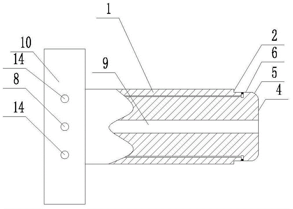
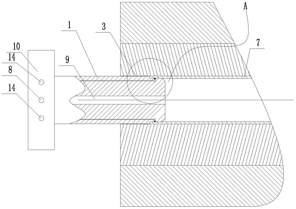
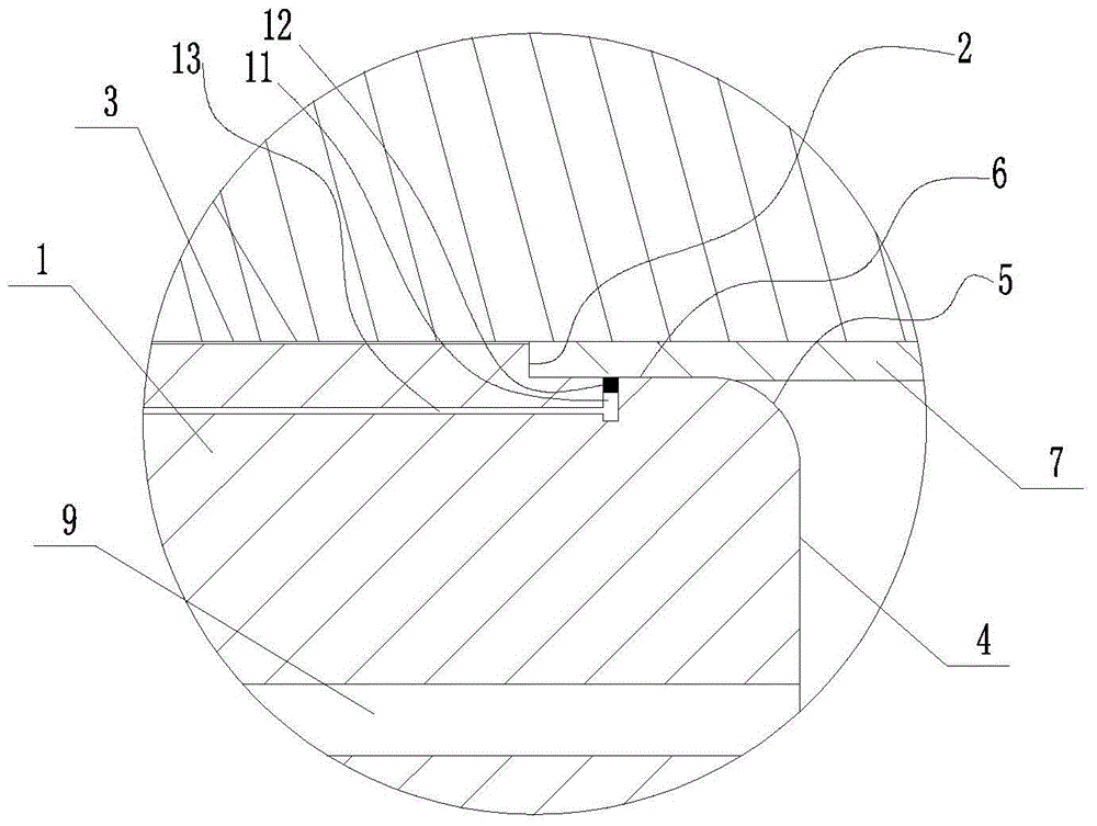
[0014] The punch for internal high pressure forming of the present invention includes a body 1, at least one end of the body 1 is a cylinder, and the one end is provided with an annular plane 2, and the annular plane 2 divides the one end into left and right parts, and the left part is used to communicate with The punch inlet and outlet holes 3 of the mold for internal high pressure forming are clearance fit, the right part includes the end face 4 of the one end, and the right part is a guide section 5 and a sealing section 6 in sequence from right to left along the axial direction, and the sealing section 6 is used to communicate with The processed pipe fitting 7 formed by internal high pressure has an interference fit, and the guide section 5 is a rounded transition part provided between the side of the right part and the end surface 4 .

[0015] An annular groove 11 is provided on the sealing section 6 of ...


PUM

PropertyMeasurementUnit
radiusaaaaaaaaaa

Abstract

The invention provides a punch pin for internal high pressure molding. The punch pin is good in sealing effect and simpler in structure, facilitates stable forming, and comprises a body (1), wherein at least one end of the body (1) is a cylinder, and an annular plane (2) is arranged at the end and is used for dividing the end into a left part and a right part; the left part is used for being in clearance fit with a punch pin inlet / outlet hole (3) of a mold for the internal high pressure forming; the right part comprises an end face (4) of the end; a guide section (5) and a sealing section (6) are sequentially arranged on the right part from right to left along the axial direction; the sealing section (6) is used for being in interference fit with a machined pipe fitting (7) which is formed under internal high pressure; the guide section (5) is a fillet transition part which is arranged between the side surface of the right part and the end face (4).

Description

technical field [0001] The invention relates to the technical field of internal high pressure forming devices, in particular to a punch for internal high pressure forming. Background technique [0002] Internal high pressure forming technology has been researched for many years, and there are many plans for patent applications, such as the invention application with the application publication number CN 102764809 A, the utility patent with the authorized announcement number CN 201659188 U, the invention application with the publication number CN101011715 A, etc. The principle and advantages of internal high pressure forming have been fully analyzed. Among these schemes, we have generally seen three schemes for the punch for internal high pressure forming (also commonly called plug for internal high pressure forming in the industry). 1. The invention application with application publication number CN 102764809 A discloses a gasket structure, which relies on the gasket or seal...

Claims


Application Information

Patent Timeline
Patent Type & Authority Patents(China)
IPC IPC(8): B21D26/047B21D26/045
Inventor 吴江葛干辉
Owner NINGBO SIMING AUTOMOBILE TECH
Learn More