Automatic tool conveying assembly line

A technology of assembly line and tooling, which is applied in the direction of transportation, packaging, roller table, etc., can solve the problems of transmission stability, motor burnout, damage to tooling, etc., and achieve the effect of improving stability, preventing abnormal friction, and avoiding wear

Inactive Publication Date: 2018-10-16
WEIFANG LOKOMO PRECISION IND
View PDF6 Cites 10 Cited by
  • Summary
  • Abstract
  • Description
  • Claims
  • Application Information

AI Technical Summary

Problems solved by technology

[0002] In the factory automation production process, the conveyor line is widely used. Most of the existing conveyor lines are driven by chains to drive multiple transmission shafts. The transmission wheel on the transmission shaft drives the tooling placed on it through friction. The tooling is transported to the required position, but when the tooling is blocked or stuck behind due to a fault, the transmission wheel on the drive shaft will continue to rub against the tooling, which will damage the tooling or cause the motor load to increase and burn out, and the stability of the transmission will also be affected.

Method used


Image

  • Automatic tool conveying assembly line
  • Automatic tool conveying assembly line
  • Automatic tool conveying assembly line

Examples


Embodiment 1

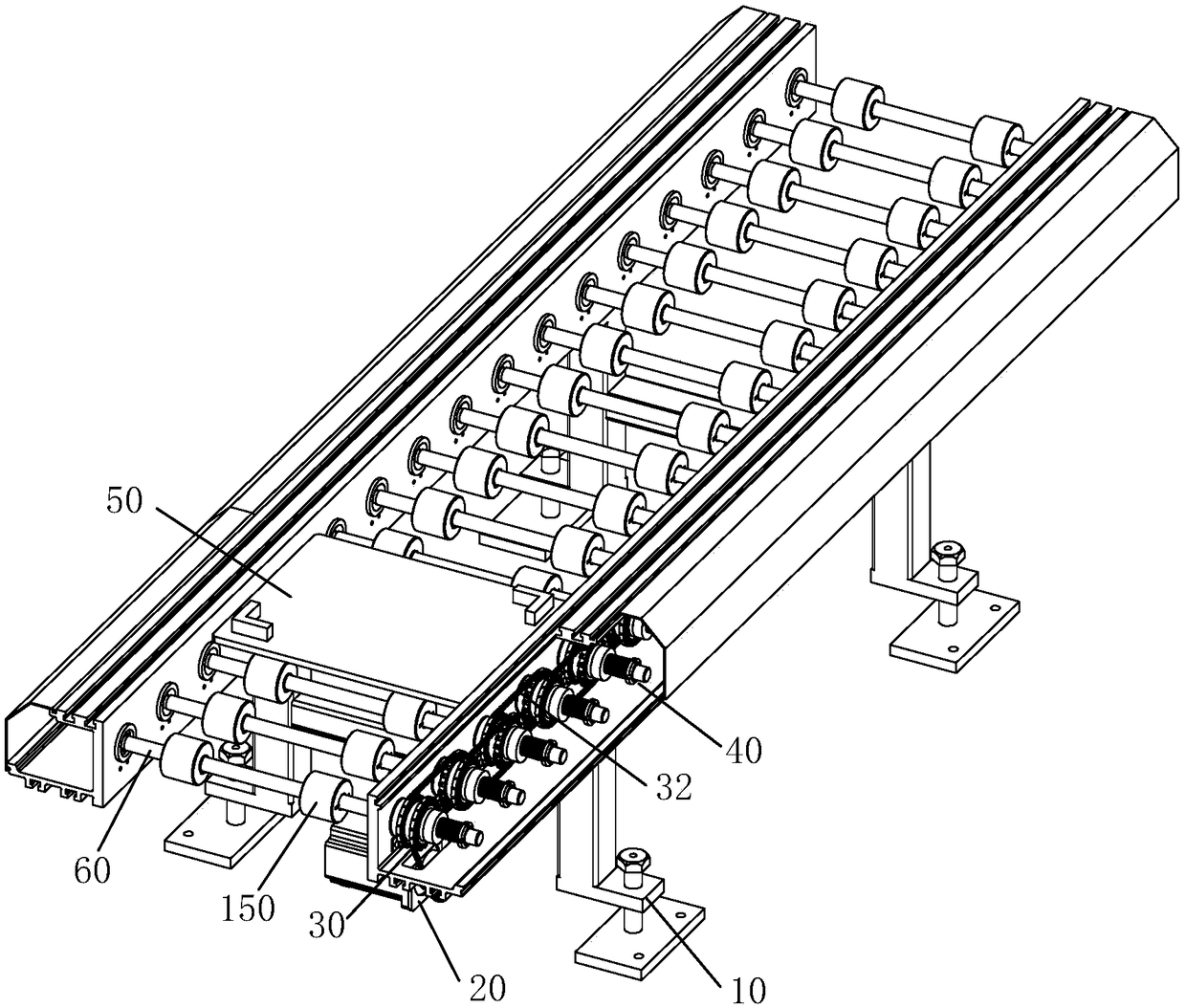
[0043] like figure 1 and figure 2 As shown, an automated tooling conveying assembly line includes an assembly line support 10, a motor power assembly 20, the motor power is transmitted to the transmission shaft assembly 40 through the transmission chain 30, and the adjacent transmission shaft assembly 40 transmits the power of the motor through the cascade chain 32 in sequence, and the transmission The transmission wheel 150 on the shaft assembly 40 drives the tooling 50 through friction to realize automatic forward and backward transportation.

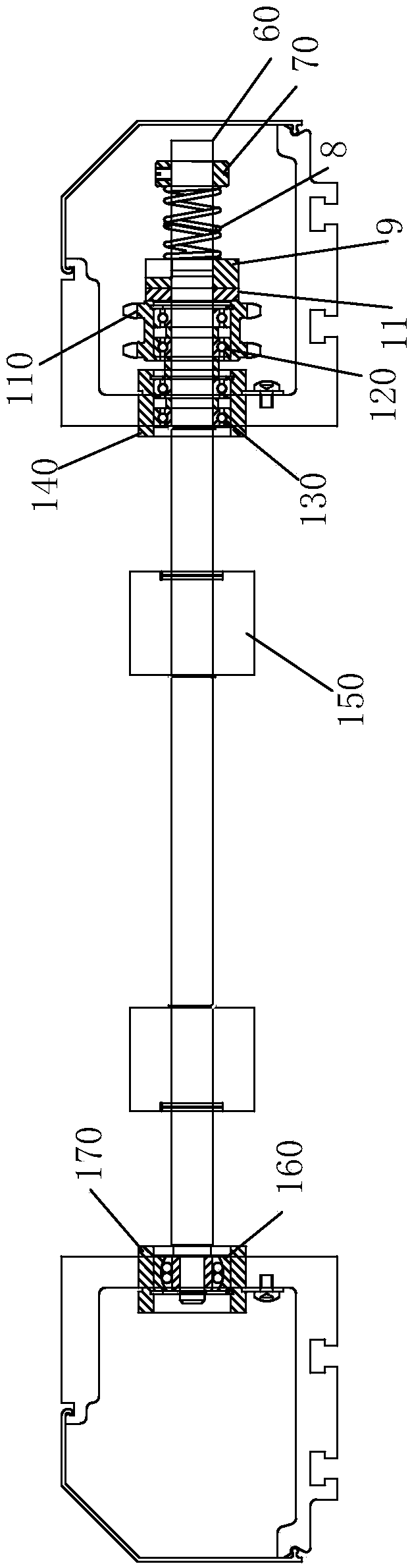
[0044] In this embodiment, the assembly line support 10 is provided with multiple sets of drive shaft assemblies 40 arranged side by side, and each set of drive shaft assemblies includes a drive shaft 60 and a drive wheel 150 disposed on the drive shaft 60 . One end of each transmission shaft 60 is installed and fixed to one side of the assembly line support 10 through the third bearing holder 140, and the third bearing 130 is also ...

Embodiment 2

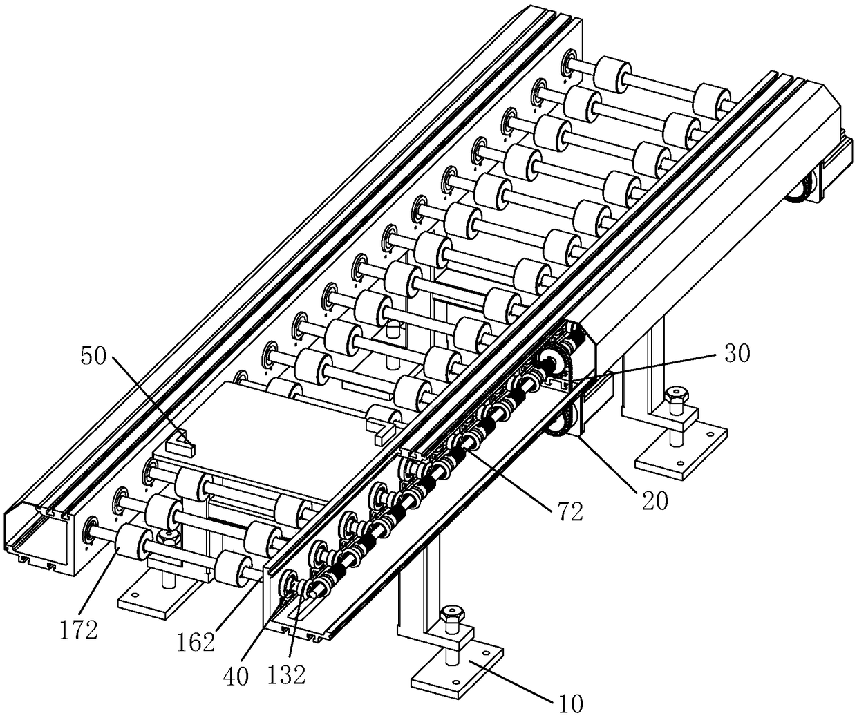
[0050] like image 3 and Figure 4 As shown, an automated tooling conveying assembly line includes an assembly line support 10, a motor power assembly 20, and the motor power is transmitted to the driving shaft 72 through the transmission chain 30. The gear 132 is meshed for transmission.

[0051] Same as the first embodiment, the assembly line support 10 is provided with multiple sets of drive shaft assemblies 40 arranged side by side, and each set of drive shaft assemblies includes a drive shaft 162 and a drive wheel 172 disposed on the drive shaft 162 . One end of each transmission shaft 162 is installed and fixed to one side of the assembly line support 10 by the third bearing holder 142, and the third bearing 152 is also installed in the third bearing holder 142; the other end of the transmission shaft 162 passes through the third bearing The fixing seat 182 is installed and fixed on the other side of the assembly line support 10 , and a third bearing 192 is installed i...


PUM


Abstract

The invention discloses an automatic tool conveying assembly line. The automatic tool conveying assembly line comprises assembly line supports. A motor power assembly, a shaft driving assembly and a plurality of transmission shaft assemblies which are arranged side by side are mounted on the assembly line supports. Each transmission shaft assembly comprises a transmission shaft. The shaft drivingassembly comprises a power transmission piece, a shaft connecting piece and a transmission friction assembly. The transmission friction assembly is connected with the power transmission piece and theshaft connecting piece through frictional transmission. The frictional transmission force of the transmission friction assembly is smaller than or equal to the maximum power load of the motor power assembly. When the frictional force exceeds the maximum frictional force of the transmission friction assembly under the condition that a tool is blocked or gets stuck, power transmitted through friction is cut off, the power transmission piece still rotates, and the load of the motor is not changed, so that the motor is prevented from being burnt down; and meanwhile, the cut-off power stops the transmission shaft from rotating, and thus, abrasion of the tool is avoided. Thus, abnormal abrasion between transmission wheels and the tool is prevented, and the operating stability of the assembly line is improved.

Description

technical field [0001] The invention relates to the technical field of conveying lines, in particular to an automatic tooling conveying line. Background technique [0002] In the factory automation production process, the conveyor line is widely used. Most of the existing conveyor lines are driven by chains to drive multiple transmission shafts. The transmission wheel on the transmission shaft drives the tooling placed on it through friction. The tooling is transported to the required position, but when the tooling is blocked or stuck behind due to a fault, the transmission wheel on the drive shaft will continue to rub against the tooling, which will damage the tooling or cause the motor load to increase and burn out, and the stability of the transmission will also be affected. . Contents of the invention [0003] In view of the above deficiencies, the technical problem to be solved by the present invention is to provide an automatic tooling conveying assembly line, which...

Claims


Application Information

Patent Timeline
Patent Type & Authority Applications(China)
IPC IPC(8): B65G13/07B65G13/11
CPCB65G13/07B65G13/11
Inventor 韩海庆
Owner WEIFANG LOKOMO PRECISION IND
Why Eureka
Try Eureka