Sequential relays capable of controlling multiple loads

A relay and multi-load technology, applied in the direction of relays, electromagnetic relays, detailed information of electromagnetic relays, etc., can solve the problems of single control, single function, and obsolete structure, and achieve the effect of reducing production costs and improving reliability

Active Publication Date: 2017-11-17
蒋胜泉 +1
View PDF4 Cites 0 Cited by
  • Summary
  • Abstract
  • Description
  • Claims
  • Application Information

AI Technical Summary

Problems solved by technology

However, regardless of the type of relay, existing relays can only control a single load or circuit. If multiple loads or circuits are to be controlled at the same time, multiple relays need to be installed, which will inevitably lead to the complexity and complexity of the control circuit. cost increase
On the other hand, as far as the most widely used electromagnetic relay is concerned, it only has one moving contact and one static contact, so it can only control a single load or circuit. sex change

Method used


Image

  • Sequential relays capable of controlling multiple loads
  • Sequential relays capable of controlling multiple loads
  • Sequential relays capable of controlling multiple loads

Examples


Embodiment 1

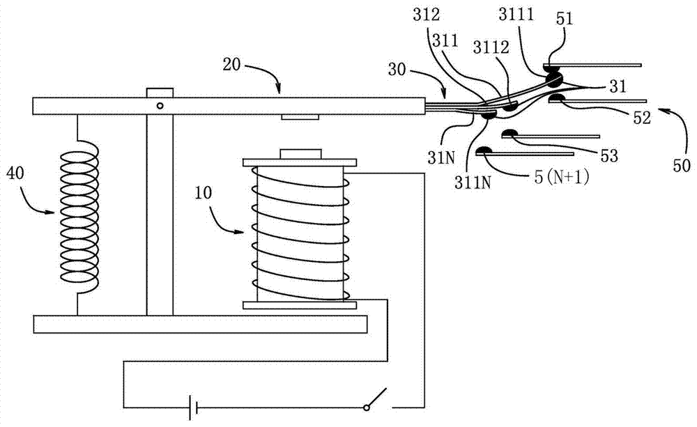
[0018] refer to Figure 1 to Figure 6 , the multi-load controllable sequential relay of the present invention includes an electromagnet 10, an armature 20, a spring 40, a movable contact 31 and a static contact 50, and each component forms an electromagnetic relay.

[0019] Such as Figure 1 ~ Figure 3 As shown, the gist of the present invention is that a plurality of conductive elastic pieces with movable contacts and static contacts corresponding to the movable contacts are arranged at one end of the armature 20 . The plurality of conductive elastic pieces 30 include a first conductive elastic piece 311 to an Nth conductive elastic piece 31N, and the number of conductive elastic pieces is determined according to the load to be controlled by the timing relay. exist Figure 1 ~ Figure 3 In the illustrated embodiment, a first conductive elastic piece 311 and a second conductive elastic piece 312 are provided at one end of the armature 20, and the first conductive elastic piec...

Embodiment 2

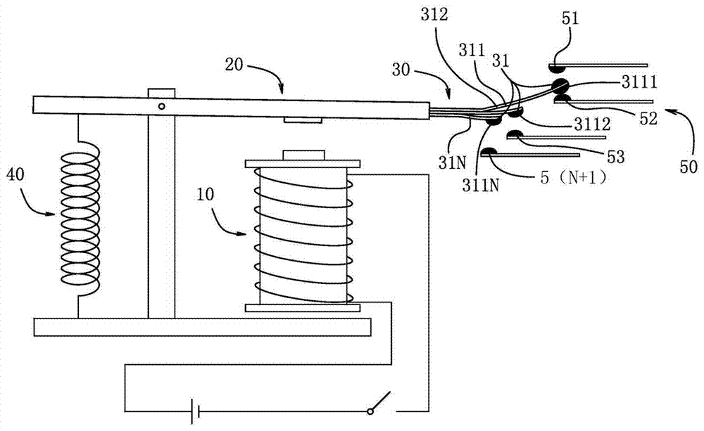
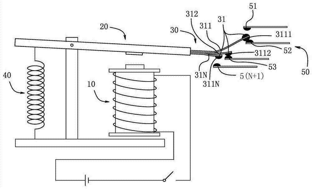
[0022] Its basic structure is the same as that of Embodiment 1, the difference is that the plurality of conductive elastic pieces 30 are dislocated in the horizontal direction, one end of which is fixedly connected to the armature 20, and the other end extends forward. Such as Figure 4 ~ Figure 6 As shown, the plurality of conductive elastic pieces 30 include the first conductive elastic piece 311 to the Nth conductive elastic piece 31N, and the plurality of conductive elastic pieces 30 are arranged at the front end of the armature 20 in a horizontal direction, that is, the plurality of conductive elastic pieces 30 are horizontally The directions are dislocated at a certain angle, and the lengths of the multiple conductive elastic pieces 30 can be the same or different. The plurality of static contacts 50 are respectively arranged below the corresponding movable contacts 31 of the respective conductive elastic pieces. The working process of the sequential relay is the same a...


PUM


Abstract

A time sequence relay capable of controlling multiple loads comprises an electromagnet, an armature, a spring, movable contacts and fixed contacts. The time sequence relay is characterized in that a plurality of conductive spring pieces are arranged at one end of the armature, one movable contact is arranged at the end of each conductive spring piece, one fixed contact is arranged below the movable contact of each conductive spring piece, and the fixed contacts are electrically connected with the multiple loads respectively, so that when the armature is attracted by the electromagnet to move downwards, the movable contacts on the conductive spring pieces make contact with or are separated from the corresponding fixed contacts in a time sequence, and the multiple loads are switched on in the time sequence; after a power failure, the armature moves upwards under the effect of the spring, so that the movable contacts are separated from the fixed contacts, and the loads are switched off. According to the time sequence relay, the multiple loads are switched on in the time sequence, so that electrical devices needing to be switched on in a certain sequence are controlled, and the time sequence relay is simple in structure and low in cost.

Description

【Technical field】 [0001] The invention relates to a relay for electric control, in particular to a sequential relay capable of controlling multiple loads which conducts multiple loads respectively in time sequence. 【Background technique】 [0002] Relay is an automatic switching element with isolation function, which is widely used in remote control, telemetry, communication, automatic control, mechatronics and power electronic equipment, and is one of the most important control elements. There are many types of relays, including electromagnetic relays, solid state relays, temperature relays, reed relays, time relays, high frequency relays and many other types. However, regardless of the type of relay, existing relays can only control a single load or circuit. If multiple loads or circuits are to be controlled at the same time, multiple relays need to be installed, which will inevitably lead to the complexity and complexity of the control circuit. cost increase. On the othe...

Claims


Application Information

Patent Timeline
Patent Type & Authority Patents(China)
IPC IPC(8): H01H50/60
CPCH01H50/60
Inventor 蒋胜泉袁利
Owner 蒋胜泉
Why Eureka
Try Eureka