Switch cabinet with component installation plate capable of automatically moving

A technology for automatically moving and installing panels, applied in the field of switch cabinets, can solve problems such as inconvenience, affecting maintenance work efficiency, and operator discomfort, and achieve the effect of improving work efficiency

Active Publication Date: 2015-01-28
佛山市雅恒电气设备有限公司
View PDF5 Cites 8 Cited by
  • Summary
  • Abstract
  • Description
  • Claims
  • Application Information

AI Technical Summary

Problems solved by technology

[0002] At present, most of the electrical components in the switch cabinet are installed on a mounting plate, and the mounting plate is then fixed on the back panel of the cabinet, or the electrical components are directly installed in the cabinet. Or during fault maintenance, the operator needs to put his upper body into the cabinet to maintain and check the devices in the cabinet, and only one operator can be accommodated, which is very inconvenient, brings discomfort to the operator, and affects Maintenance work efficiency

Method used


Image

  • Switch cabinet with component installation plate capable of automatically moving
  • Switch cabinet with component installation plate capable of automatically moving

Examples


Embodiment Construction

[0010] The present invention will be described in further detail below through specific implementation examples and in conjunction with the accompanying drawings.

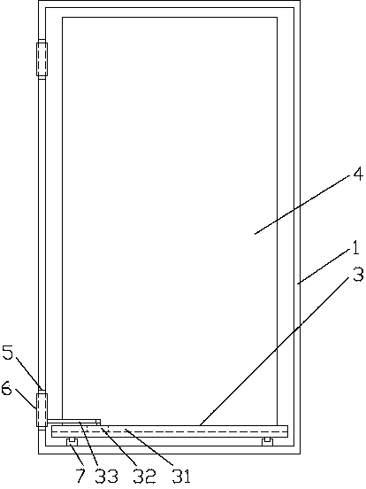
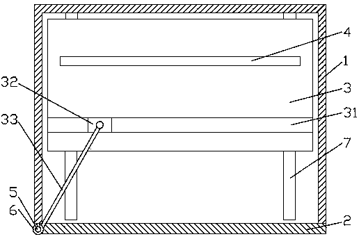
[0011] figure 1 , figure 2 It shows the automatic movable switchgear for the component mounting plate provided by the present invention, including a cabinet body 1, a cabinet door 2 rotationally connected with the cabinet body 1, a sliding plate 3 located at the inner bottom of the cabinet body 1 and slidingly arranged, driving the sliding plate 3 to The driving mechanism that slides on the side of the cabinet door, the component mounting plate 4 located on the slide plate 3; the slide plate 3 is provided with a chute 31 that is consistent with the direction of the cabinet door 2 when the cabinet door 2 is closed, and the drive mechanism includes a drive block 32 and a drive rod 33, the driving block 32 is located in the chute 31, one end of the driving rod 33 is hinged with the driving block 32, and the other en...


PUM


Abstract

The invention discloses a switch cabinet with a component installation plate capable of automatically moving, and belongs to the technical field of switch cabinets. The switch cabinet comprises a cabinet body, a cabinet door, a sliding plate, a driving mechanism and the component installation plate. The cabinet door is rotationally connected with the cabinet body, the sliding plate is located at the bottom inside the cabinet body and arranged in a sliding mode, the driving mechanism drives the sliding plate to slide towards the cabinet door, and the component installation plate is located on the sliding plate. A sliding groove in the same direction as the closed cabinet door is formed in the sliding plate. The driving mechanism comprises a driving block and a driving rod. The driving block is located in the sliding groove. One end of the driving rod is hinged to the driving block, and the other end of the driving rod and the cabinet door are fixedly connected. According to the switch cabinet, the component installation plate automatically moves along with opening and closing of the cabinet door, the installation plate does not need to be fixed to the cabinet body, a maintainer does not need to enter the cabinet body any more during maintenance, maintenance is more convenient and faster, and the working efficiency is improved.

Description

technical field [0001] The invention relates to the technical field of switch cabinets, in particular to a switch cabinet with an automatically movable component mounting plate. Background technique [0002] At present, most of the electrical components in the switch cabinet are installed on a mounting plate, and the mounting plate is then fixed on the back panel of the cabinet, or the electrical components are directly installed in the cabinet. Or during fault maintenance, the operator needs to put his upper body into the cabinet to maintain and check the devices in the cabinet, and only one operator can be accommodated, which is very inconvenient, brings discomfort to the operator, and affects Maintenance work efficiency. Contents of the invention [0003] The object of the present invention is to provide an automatic movable switchgear for component installation boards to solve the above problems. [0004] In order to achieve the purpose of the present invention, the ...

Claims


Application Information

Patent Timeline
Patent Type & Authority Applications(China)
IPC IPC(8): H02B1/26
CPCH02B1/26
Inventor 陈刚
Owner 佛山市雅恒电气设备有限公司
Why Eureka
Try Eureka