Glass cleaning equipment for building

A cleaning equipment and construction technology, applied in the field of construction glass cleaning equipment, can solve the problems of low work efficiency, high labor intensity, waste of labor, etc., and achieve the effect of improving work efficiency

Pending Publication Date: 2021-04-06
许书倩
View PDF6 Cites 5 Cited by
  • Summary
  • Abstract
  • Description
  • Claims
  • Application Information

AI Technical Summary

Problems solved by technology

[0004] In order to overcome the shortcomings of manual glass wiping, low work efficiency, waste of labor, and high labor intensity, the technical problem to be solved is to provide a building glass cleaning equipment that can realize automatic cleaning and wiping

Method used


Image

  • Glass cleaning equipment for building
  • Glass cleaning equipment for building
  • Glass cleaning equipment for building

Examples


Embodiment 1

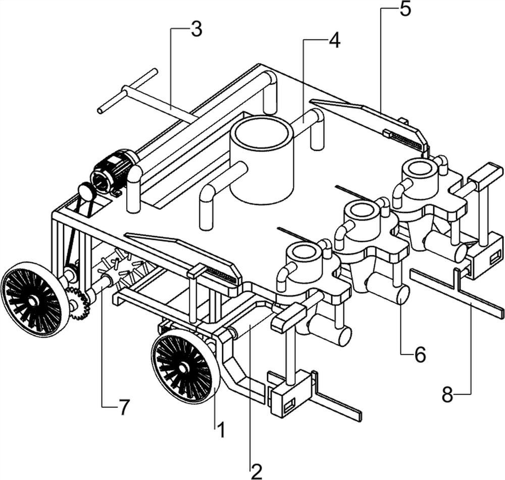
[0063] A kind of building glass cleaning equipment, such as figure 1 As shown, it includes a rotating wheel 1, a first rotating shaft 2, a power mechanism 3 and a flushing mechanism 4, and the left and right sides of the lower part of the power mechanism 3 are connected with the first rotating shaft 2 in a rotational manner, and the first rotating shaft 2 is provided on the front and rear sides. There is a rotating wheel 1, and a flushing mechanism 4 is provided on the power mechanism 3.

[0064] When people need to clean the glass, the glass is first placed on the right side of the device, then water is poured into the flushing mechanism 4, and then the power mechanism 3 is started, and the power mechanism 3 drives the first rotating shaft 2 and the rotating wheel 1 to rotate continuously, driving the machine. The equipment moves to the right, so that the washing mechanism 4 cleans the glass, and after completion, the power mechanism 3 can be closed.

Embodiment 2

[0066] On the basis of Example 1, such as Figure 2-3 As shown, the power mechanism 3 includes a bearing seat 30, a mounting plate 31, a servo motor 32, and a transmission assembly 33. The four sides of the bottom of the mounting plate 31 are provided with a bearing seat 30, and the bearing seat 30 is rotationally connected with the first rotating shaft 2. A servo motor 32 is connected to the top left front side of the plate 31 , and a transmission assembly 33 is connected between the output shaft of the servo motor 32 and the front side of the first rotating shaft 2 on the left.

[0067] When the device needs to be moved, start the servo motor 32, the output shaft of the servo motor 32 rotates to drive the transmission assembly 33, the first rotating shaft 2 and the rotating wheel 1 to rotate continuously, and then drives the device to move to the right. When not in use, turn off the servo motor 32 That's it.

[0068] The flushing mechanism 4 includes a first L-shaped rod 40...

Embodiment 3

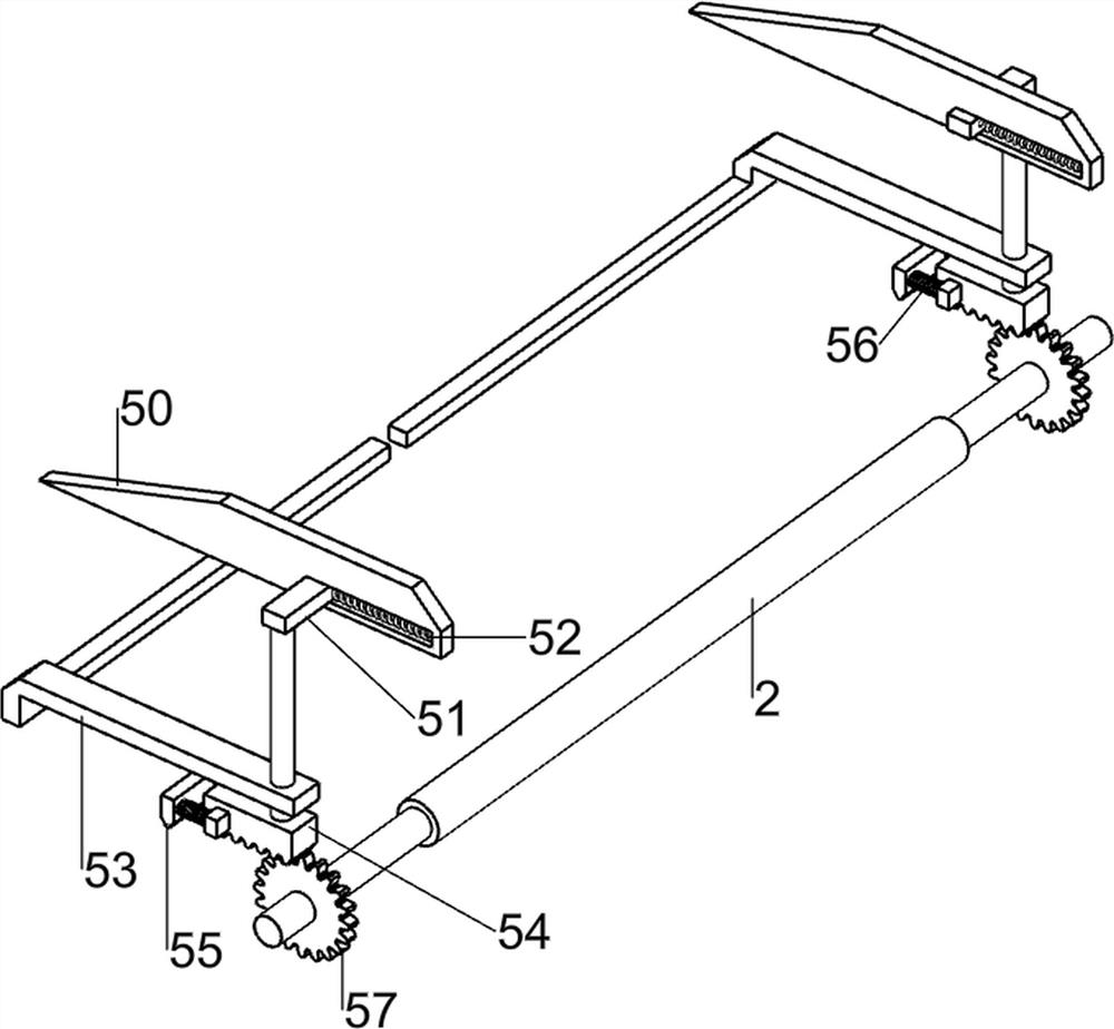
[0071] On the basis of Example 2, such as Figure 4-9 As shown, the opening and closing mechanism 5 is also included, and the opening and closing mechanism 5 includes a first slide rail 50, a slider 51, a first spring 52, a forward rod 53, a first rack 54, a second rack 55, a second rack Spring 56 and the first gear 57, the first slide rail 50 is all connected with the front and rear sides in the middle of the mounting plate 31 top, and slide block 51 is all slidingly connected on the first slide rail 50, the right side of slide block 51 and the first slide rail 50 are provided with the first spring 52, the bottom of the slide block 51 is provided with the advance rod 53, the left side of the advance rod 53 is connected with the baffle plate 43, the right side of the bottom of the advance rod 53 is connected with the first rack 54, the first The left side of the rack 54 is slidably connected with a second rack 55, two second springs 56 are arranged between the right side of th...


PUM


Abstract

The invention relates to cleaning equipment, in particular to glass cleaning equipment for building. The technical problem to be solved is to provide the glass cleaning equipment for a building, which is capable of realizing automatic cleaning and wiping. The glass cleaning equipment for the building comprises a first rotating shaft, a power mechanism with the two sides of a part thereof being rotationally connected with the first rotating shaft, rotating wheels arranged on the two sides of the first rotating shaft, and a flushing mechanism arranged on the power mechanism. Through cooperation of the power mechanism and the flushing mechanism, the glass cleaning equipment can be automatically moved while glass is cleaned, the working efficiency of people is improved, through cooperation of a detergent adding mechanism and a wiping mechanism, detergent can be automatically sprayed out, the glass is cleaned more cleanly, and then the glass is wiped.

Description

technical field [0001] The invention relates to a cleaning device, in particular to a cleaning device for building glass. Background technique [0002] The types of dirt on the glass surface generally include dust, dry solids, oil stains, etc. Only by removing them from the glass surface can the glass be kept clean and bright. At present, the method of cleaning glass is mostly manual wiping, which is usually divided into two steps: first wipe the glass surface with a damp cloth to remove the dirt, and then dry it with a dry cloth to make the glass bright. Although this method can cleanly remove the dirt to achieve cleaning, the work efficiency is low and the labor is wasted, and the labor intensity is relatively large. [0003] At present, in order to change the traditional cleaning method, a building glass cleaning equipment capable of automatic cleaning and wiping has been developed. Contents of the invention [0004] In order to overcome the shortcomings of low work e...

Claims


Application Information

Patent Timeline
Patent Type & Authority Applications(China)
IPC IPC(8): B08B3/02
CPCB08B3/024
Inventor 不公告发明人
Owner 许书倩
Why Eureka
Try Eureka