Method and device for gesture control camera rotation and infrared gesture sensor
A gesture control, infrared gesture technology, applied in the field of control, can solve the problems of wasting power resources, uncertainty, motor idling, etc., to achieve the effect of improving accuracy
- Summary
- Abstract
- Description
- Claims
- Application Information
AI Technical Summary
Problems solved by technology
Method used
Image
Examples
Embodiment 1
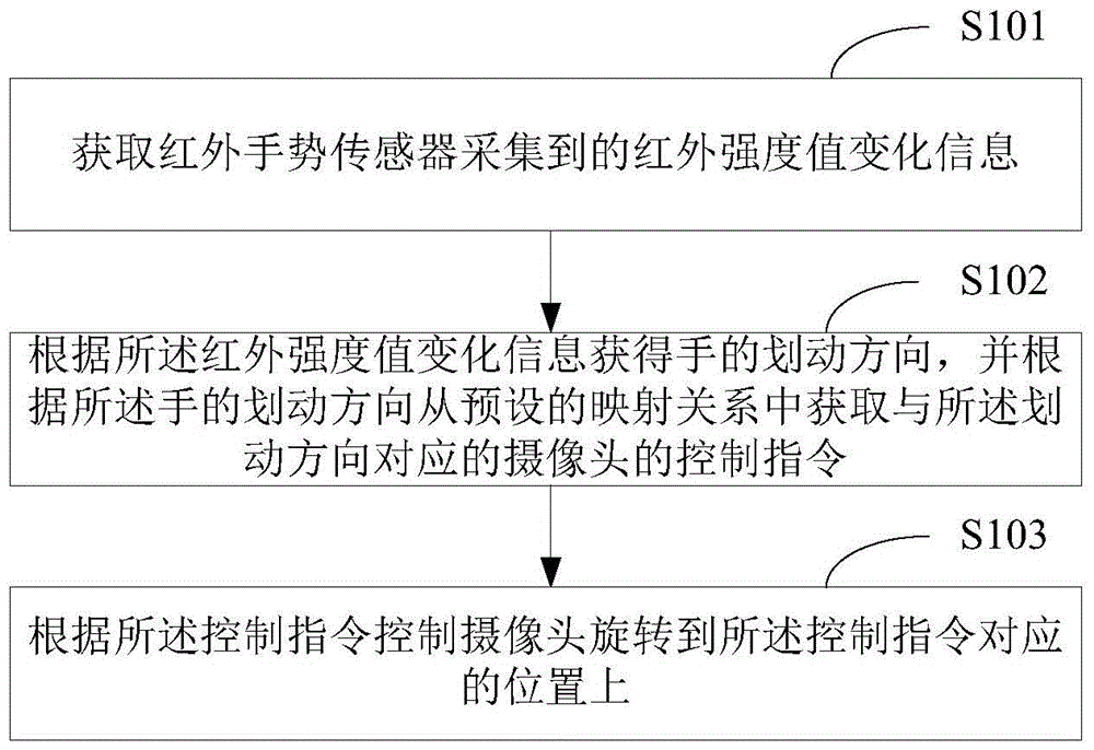
[0060] figure 1 It shows the first implementation flow chart of the method for controlling camera rotation by gestures provided by Embodiment 1 of the present invention; for the convenience of description, only the parts related to the present invention are shown.
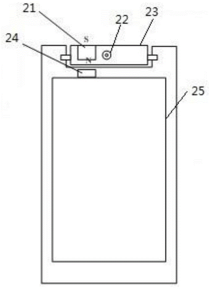
[0061] In this embodiment, the method is applied to user equipment with a rotatable camera, including but not limited to mobile terminals such as mobile phones, tablet computers, and iPads. Wherein, in the rotatable camera, the camera is arranged on a rotatable device, and the rotatable device is located on the mobile terminal; a magnet is arranged on the rotatable device, and the magnet deviates from the rotatable device. The rotating shaft; and the digital Hall sensor is arranged on the main body of the mobile terminal and is arranged opposite to the magnet, which is used to sense the change of the magnetic field caused by the rotation of the magnet with the rotatable device, so as to determine the current offset...
Embodiment 2
[0078] Figure 4 It shows the first implementation process of step S103 in the method for controlling camera rotation with gestures provided by Embodiment 2 of the present invention. For the convenience of description, only the parts related to the present invention are shown.
[0079] When the digital Hall sensor monitors the offset angle of the camera, it is mainly realized by measuring the magnetic induction intensity of the magnet. Such as figure 2 In the structure shown, the distance between the digital Hall sensor and the magnet is the farthest, the magnetic field strength sensed is the weakest, the absolute value of the output value of the digital Hall sensor is the smallest, and the corresponding camera angle is 0 degrees. When the S pole of the magnet rotates to the N pole side, the distance between the digital Hall sensor and the magnet is the shortest, the sensed magnetic field strength is the strongest, the absolute value of the output value of the digital Hall s...
Embodiment 3
[0094] Image 6 It shows the second implementation process of step S103 in the method for controlling camera rotation by gesture provided in Embodiment 3 of the present invention. For ease of illustration, only the parts relevant to the present invention are shown.
[0095] In this embodiment, the camera control command is to control the camera to rotate to the front position.
[0096] Such as Image 6 As shown, step S103 includes:
[0097] In step S601, the initial output value of the digital Hall sensor is collected.
[0098] In step S602, it is judged whether the initial output value is smaller than a lower threshold.
[0099] Preferably, the lower threshold is the corresponding output value of the digital Hall sensor when the camera angle is 110 degrees. Therefore, when the collected initial output value of the digital Hall sensor is less than the lower threshold, it is determined that the camera is at the rear position, and step S403 is executed.
[0100] In step S6...
PUM
 Abstract
Description
Claims
Application Information
 - R&D
- Intellectual Property
- Life Sciences
- Materials
- Tech Scout
- Unparalleled Data Quality
- Higher Quality Content
- 60% Fewer Hallucinations
Browse by: Latest US Patents, China's latest patents, Technical Efficacy Thesaurus, Application Domain, Technology Topic, Popular Technical Reports.
© 2025 PatSnap. All rights reserved.Legal|Privacy policy|Modern Slavery Act Transparency Statement|Sitemap|About US| Contact US: help@patsnap.com


