Spine dynamic growth rod

A spine dynamic and growing rod technology, applied in the field of medical devices, can solve the problems of complex structure, large volume, too many product parts, etc., and achieve the effect of avoiding pain and shortening operation time

Active Publication Date: 2015-02-04
常州亨杰医疗器械有限公司
View PDF5 Cites 2 Cited by
  • Summary
  • Abstract
  • Description
  • Claims
  • Application Information

AI Technical Summary

Problems solved by technology

However, because the structure of the product is relatively complex, there are many parts and the volume is large, and the assembled product has the risk of falling off due to too many parts, the operation is troublesome and the installation time is relatively long, which will cause doctors to use it during use. Inconvenience

Method used


Image

  • Spine dynamic growth rod
  • Spine dynamic growth rod
  • Spine dynamic growth rod

Examples


Embodiment Construction

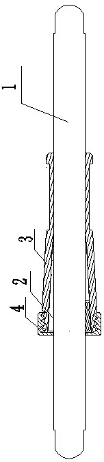
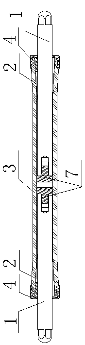
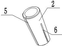
[0013] like figure 1 , figure 2 , image 3 As shown, a dynamic growth rod for the spine comprises at least one connecting rod 1, elastic ferrule 2, sleeve 3 and cover plate 4, the shape of the elastic ferrule 2 is tapered, and the unilateral taper of the elastic ferrule 2 is 2°—10°, the elastic ferrule 2 is provided with a through groove 5 along the axial direction, and the elastic ferrule 2 is also provided with at least one groove 6 along the axial direction, and the notch of the groove 6 is set on the tapered elastic clamp On the small opening of the sleeve 2, the connecting rod 1 is covered with an elastic ferrule 2, and the connecting rod 1 is arranged in the casing 3 through the interference fit of the elastic ferrule 2, and the casing 3 is connected to the cover plate 4 by threads.

[0014] Among them such as figure 1 and image 3 As shown, the number of connecting rod 1 is 1, one end of the sleeve 3 is a tapered hole, the other end of the sleeve 3 is a round hole,...


PUM


Abstract

The invention relates to the technical field of medical apparatuses, in particular to a spine dynamic growth rod, which comprises at least one connecting rod, one conical elastic clamping sleeve, one sleeve cylinder and one cover plate. When one connecting rod is used, a conical hole is formed in one end of the sleeve cylinder, a circular hole is formed in the other end of the sleeve cylinder, the connecting rod is arranged in the sleeve cylinder in a clearance fit way through the conical elastic clamping sleeve, and the sleeve cylinder is connected with a cover plate; when two connecting rods are used, conical holes are formed in the two ends of each sleeve cylinder, a circular hole is formed in the middle part of each sleeve cylinder, the two connecting rods are symmetrically arranged, the symmetrical end surfaces are respectively provided with a limiting block, the two connecting rods are respectively arranged in the sleeve cylinders in the clearance fit way through the corresponding conical elastic clamping sleeve, and the two ends of each sleeve cylinder are connected with the corresponding cover plate by threads. The spine dynamic growth rod has the advantages that by utilizing the simple conical structure, the dynamic growth rod grows along with the growth of a patient, so the pain of the patient caused by secondary operation and multiple operations because of growth is avoided; by selecting a one-way growth mode and a two-way growth mode, the operation time of the doctor is effectively shortened, and the foreign body sensation of the patient in the use process is effectively reduced.

Description

technical field [0001] The invention relates to the technical field of medical devices, in particular to a dynamic growth rod for the spine. Background technique [0002] It is used to treat children's orthopedic dynamic growth support rods. This field is basically blank in China. At present, the Sixth Affiliated Hospital of Xinjiang Medical University has applied for a scoliosis support growth rod for children. The Hastelloy separation rod, the upper hook is installed on the lock of the Hastelloy separation rod, the casing is set at the lower part of the Hastelloy separation rod, and the spring stopper is set at the lower part of the core rod which is movably matched with the casing, and the Hastelloy separation rod A compression spring is installed on the core rod between the lower end of the casing and the core rod spring stopper, and a post is arranged under the core rod spring stopper. When the post is matched, the hook mouth of the upper hook is upward, and the hook m...

Claims


Application Information

Patent Timeline
Patent Type & Authority Applications(China)
IPC IPC(8): A61B17/70
CPCA61B17/7002A61B17/7052A61B17/7074
Inventor 黄建平王喜戚磊
Owner 常州亨杰医疗器械有限公司
Why Eureka
Try Eureka