
A fan panel for high -rise housing flue

A technology for high-rise residences and exhaust fans, which is applied to components of pumping devices for elastic fluids, non-variable-capacity pumps, machines/engines, etc. Chimney effect, etc.

Inactive Publication Date: 2017-04-19
JINHUA VOCATIONAL TECH COLLEGE
View PDF6 Cites 0 Cited by
  • Summary
  • Abstract
  • Description
  • Claims
  • Application Information

AI Technical Summary

Problems solved by technology

[0002] The kitchens in high-rise and small high-rise residences have flue exhaust ducts, and the bathrooms have exhaust ducts. Residents of high-rise residential buildings have a consensus: when using existing ordinary exhaust fans to exhaust the flue ducts, the smoke will often flow backwards, causing pollution to the indoor air of the residents.
This is caused by the panel structure of ordinary exhaust fans. Most of the panels are arranged horizontally in the shape of multi-strips. The key is that the upper edge of the panel is hinged with the outer cover and the opening of the air outlet is obliquely downward, that is, the exhaust gas is blown into the flue when the wind force is at its maximum limit. When the direction is horizontal, most of them are downward, which causes: first, each household directly discharges the flue gas horizontally or downward to the inner wall of the flue, and the air flow keeps rebounding on the inner wall, and the different directions often form a The turbulent flow cannot form the chimney effect of the flue gas upwards in the exhaust duct of high-rise residential buildings. The upward movement of the flue gas and the downward movement of the exhaust cancel each other out, resulting in low efficiency. The turbulent flow can easily enter the room through the ordinary exhaust fan, that is, the smoke from the kitchen and the air from the bathroom flow back in, especially in low air pressure climates.

Method used


Image

  • A fan panel for high -rise housing flue
  • A fan panel for high -rise housing flue
  • A fan panel for high -rise housing flue

Examples


Embodiment Construction

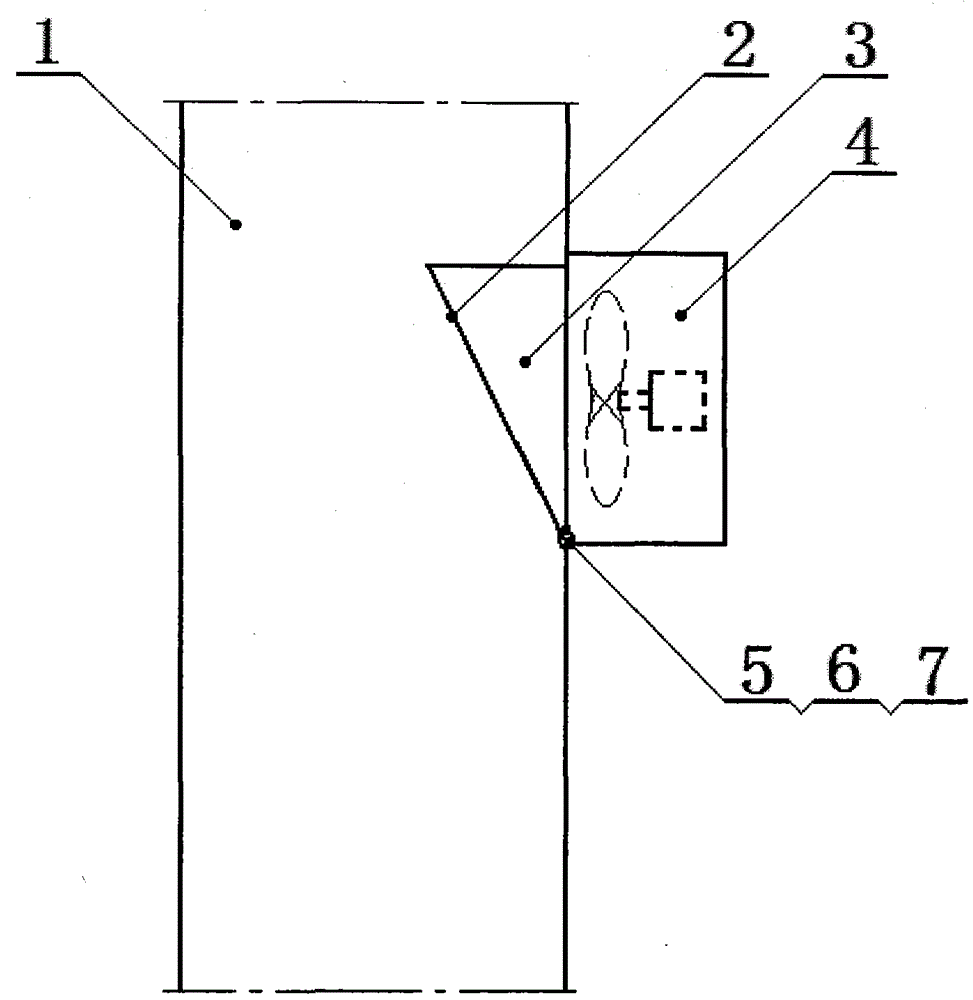
[0013] Such as figure 1 It is one of the schematic diagrams of the present invention, the panel (2) is rectangular and its two sides are connected with the triangular side panels (3), and the panel opens an upward opening when the exhaust fan is working.

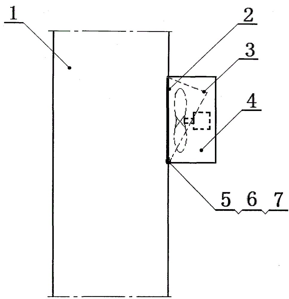
[0014] Such as figure 2 It is the second schematic diagram of the present invention. When the exhaust fan is not working, the elastic force of the stainless steel torsion spring (7) closes the air outlet of the panel (2) and the outer cover (4). At this time, the triangular side plate (3) All are also included in the outer cover (4), and the panel (2) coincides with the inner wall of the flue (1).

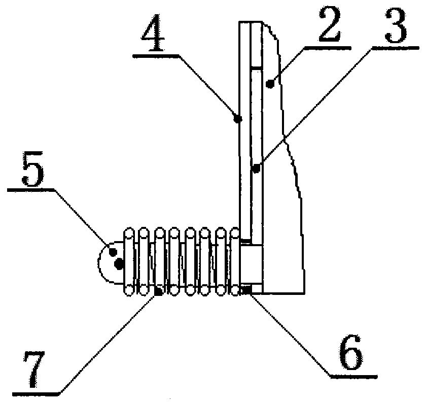
[0015] Such as image 3 yes figure 2 Partially enlarged right view schematic diagram, under the action of the stainless steel torsion spring (7), the panel (2) and the air outlet of the outer cover (4) are closed.

[0016] The exhaust fan panel for the flue of a high-rise residence is mainly composed of a panel (2), a trian...


PUM


Abstract

The invention relates to an exhaust fan part of a high-rise housing flue. An exhaust fan panel used for the high-rise housing flue is mainly composed of a panel, a triangular side plate, an outer cover, a rotating shaft, a rotating hole and a stainless steel torsion spring, wherein a motor fan is mounted in the outer cover and the outer cover is provided with an air inlet and an air outlet; the panel is located at the air outlet; the panel is rectangular and the two side edges of the panel are connected with the triangular side plates; the rotating shaft is connected with the outer side of the lower edge of the panel; the rotating hole is formed in the outer side of the lower edge of the air outlet of the outer cover; the panel is hinged to the lower edge of the air outlet of the outer cover by the rotating shaft and the rotating hole; the stainless steel torsion spring sleeves the rotating shaft; the elastic force of the stainless steel torsion spring can be used for normally closing the panel at the air outlet of the outer cover and overlapping the panel with the inner wall of the flue; when the exhaust fan works, an upward opening of the panel is opened. The exhaust fan panel used for the high-rise housing flue is simple in structure and is easy to realize; a flue gas backward flowing phenomenon can be prevented and the flue can form the chimney effect.

Description

technical field [0001] The invention relates to an exhaust fan accessory for a high-rise residence, in particular to an exhaust fan panel for the flue of a high-rise residence, which has a reasonable structure, can prevent the backflow of smoke, and can promote the chimney effect of the exhaust duct. Background technique [0002] Kitchens in high-rise and small high-rise residences have flue exhaust ducts, and toilets have exhaust ducts. Residents of high-rise residences have a consensus: when using existing ordinary exhaust fans to exhaust the flue gas, the smoke will often flow backwards, causing pollution to the indoor air of the residents. This is caused by the panel structure of ordinary exhaust fans. Most of the panels are arranged horizontally in the shape of multi-strips. The key is that the upper edge of the panel is hinged with the outer cover and the opening of the air outlet is obliquely downward, that is, the exhaust gas is blown into the flue when the wind force...

Claims


Application Information

Patent Timeline
Patent Type & Authority Patents(China)
IPC IPC(8): F04D29/00F04D29/54
CPCF04D29/002F04D29/541
Inventor 张向平赵永建曹鹦鹉张锋
Owner JINHUA VOCATIONAL TECH COLLEGE
Learn More