
Sub-wavelength metal superstructure grating and mid-infrared adjustable retroreflector

A subwavelength, retroreflector technology, applied in the field of subwavelength metal meta-gratings and mid-infrared tunable retroreflectors, can solve the problems of multiple electromagnetic losses, complex geometric structures, reduced retroreflection efficiency, etc., and achieve high retroreflection Efficiency, simple structure, performance reduction effect

Active Publication Date: 2019-11-12
SUZHOU UNIV
View PDF10 Cites 4 Cited by
  • Summary
  • Abstract
  • Description
  • Claims
  • Application Information

AI Technical Summary

Problems solved by technology

[0004] In the prior art (Song G, Cheng Q, Cui T J, Jing Y 2018 Phys.Rev.Mater.2065201), it is proposed to use a two-layer meta-grating to realize a planar retroreflective device, but for a large incident angle, the retroreflective efficiency is relatively low. Low (at 60.0° incidence, the retroreflection efficiency is less than 50%), and the coupling between the two layers of metagrating also increases the complexity of the system
In the prior art (Shen C, Díaz-Rubio A, Li J, Cummer S A 2018 Appl.Phys.Lett.112183503), a three-channel planar retroreflective device can be realized by using a meta-grating, which solves the problem of large-angle incident retroreflective devices. However, the metagrating structure contains 6 different structural units in one cycle, and the geometric structure is relatively complex.
In general, more structural units may result in more electromagnetic losses, reducing the efficiency of retroreflection

Method used


Image

  • Sub-wavelength metal superstructure grating and mid-infrared adjustable retroreflector
  • Sub-wavelength metal superstructure grating and mid-infrared adjustable retroreflector
  • Sub-wavelength metal superstructure grating and mid-infrared adjustable retroreflector

Examples


Embodiment Construction

[0033] In order to enable those skilled in the art to better understand the technical solutions in the present invention, the technical solutions in the embodiments of the present invention will be clearly and completely described below in conjunction with the drawings in the embodiments of the present invention. Obviously, the described The embodiments are only some of the embodiments of the present invention, not all of them. Based on the embodiments of the present invention, all other embodiments obtained by persons of ordinary skill in the art without making creative efforts shall fall within the protection scope of the present invention.

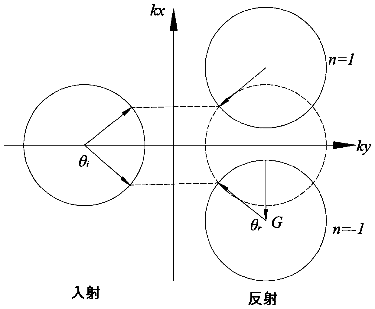
[0034] The invention provides a new and simple method for designing planar optical retroreflective devices, which reduces the loss caused by the structure while maintaining high performance. Based on the recently discovered anomalous diffraction law in the meta-grating, the present invention discloses a mid-infrared planar meta-grating ...


PUM


Abstract

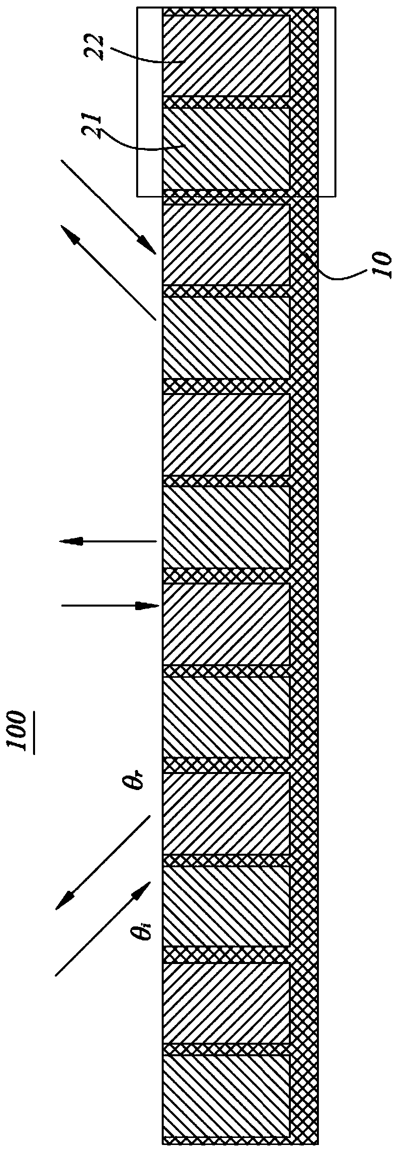
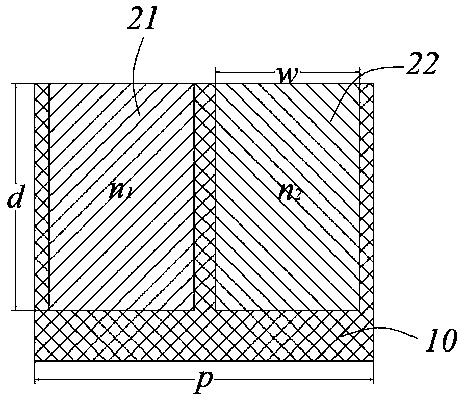
The invention discloses a sub-wavelength metal superstructure grating and a mid-infrared adjustable retroreflector. The superstructure grating comprises a metal base body, and a plurality of first grooves and second grooves which are periodically and repeatedly distributed are arranged on the metal base body; the first grooves are filled with first materials to form first structural units; secondstructural units are formed by filling the second grooves with second materials; and the first structural units and the second structural units have a reflection phase difference of pi, and a refractive index n2 of the second materials is larger than a refractive index n1 of the first materials. The reflective metal superstructure grating of the invention has simple structure and is easy to realize. Only two structural units are included in one large period, and the retroreflective function of infrared light in two channels can be realized through a simple structural design. The metal superstructure grating has high retroreflective efficiency (> 98%), which can keep high performance and reduce the loss caused by structure. Different retroreflective angles can be modulated only by changingthe period length, and the retroreflector has the characteristics of high efficiency, adjustable, dual-channel retroreflectivity and so on.

Description

technical field [0001] The invention relates to the technical field of optical devices, in particular to a sub-wavelength metal meta-grating and a mid-infrared adjustable retroreflector. Background technique [0002] How to effectively control the refraction, reflection, propagation and wavefront of light has always been one of the hot research topics in the field of optics. In the past few years, scientists have proposed the concept of graded metasurfaces, which introduce an effective wave vector κ along the direction of the interface by introducing a sudden phase covering a 2π variation within a period. According to the conservation of momentum in the tangential direction, when light is reflected and refracted on the interface, it satisfies the generalized law of reflection and refraction: k i sinθ in =k i sinθ r +κ and k i sinθ in =k t sinθ t +κ, so that the reflection, refraction and wavefront of light can be effectively controlled. The concept of local mutation...

Claims


Application Information

Patent Timeline
Patent Type & Authority Applications(China)
IPC IPC(8): G02B5/18
CPCG02B5/1861
Inventor 金霞曹燕燕徐亚东
Owner SUZHOU UNIV
Learn More