An automatic emptying device for an upper water pipe and a solar water heater with the device

An automatic emptying and water pipe technology, applied in the direction of solar thermal power generation, heating device, solar thermal device, etc., can solve the problems of poor reliability, waste of cold water backflow, waste, etc., and achieve the effect of low manufacturing cost, device avoidance, and waste avoidance.

Inactive Publication Date: 2016-03-16
ANHUI RENRENJIA SOLAR ENERGY
View PDF5 Cites 0 Cited by
  • Summary
  • Abstract
  • Description
  • Claims
  • Application Information

AI Technical Summary

Problems solved by technology

[0011] ①It cannot be used without running water;
[0012] ②When the water temperature is not high, it is easy to cause waste every time the cold water used for top pressure returns in winter;
[0013] ③ It is inconvenient to use at multiple points. When using water at the same time, you should manually cut off the electric heating power supply
[0016] Disadvantages: It does not solve the problem of wasting hot water in pipes, and it is necessary to ensure smooth indoor exhaust
[0019] Disadvantages: Cannot be used with automatic water supply controller
[0022] Disadvantages: Because the control valve is located in the lower part of the water tank, it is easily polluted by scale, which leads to control failure and poor reliability; and because the valve body often retains water, it is necessary to add electrical insulation measures in winter
It cannot be used when there is a "U"-shaped bend pipe in the user's room; it cannot be filled and discharged when the power is off; if you forget to empty it after using hot water or water, freezing will occur

Method used


Image

  • An automatic emptying device for an upper water pipe and a solar water heater with the device
  • An automatic emptying device for an upper water pipe and a solar water heater with the device

Examples


Embodiment Construction

[0035] The present invention will be further described below in conjunction with accompanying drawing:

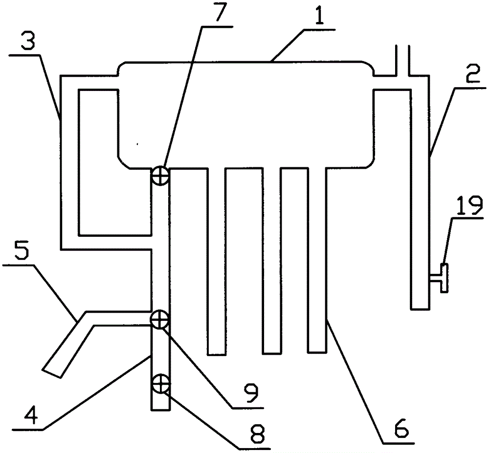
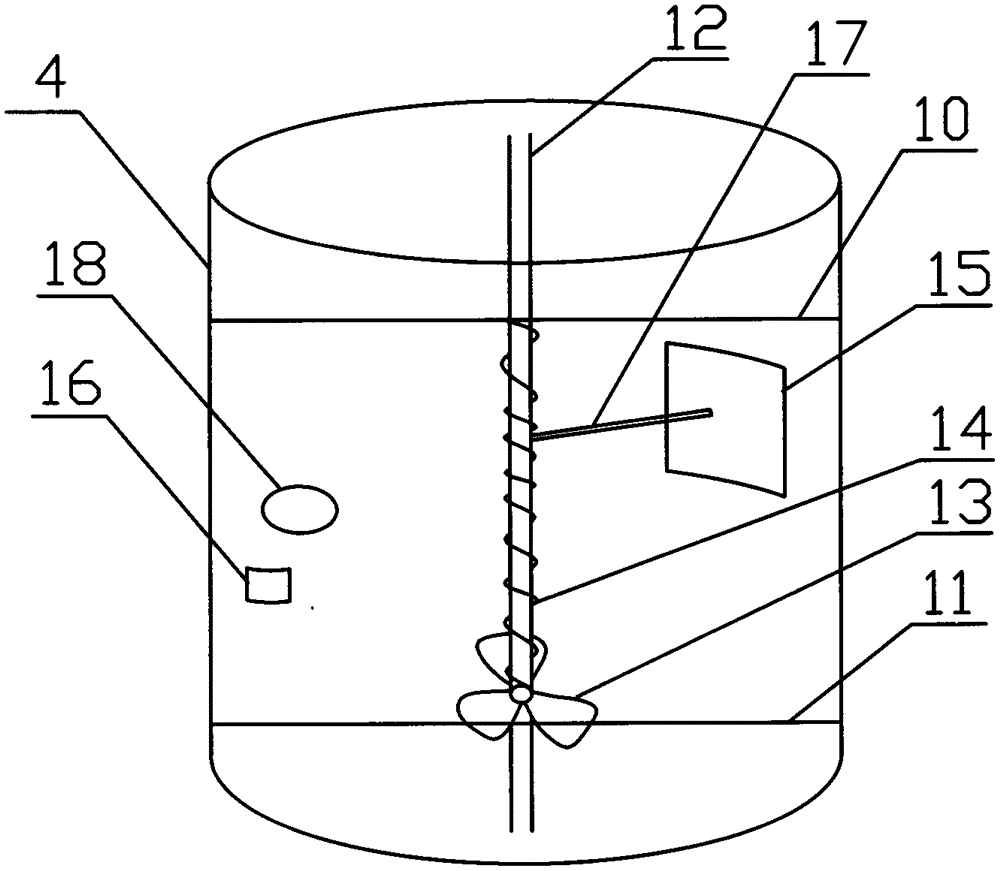
[0036] like figure 1 The shown automatic emptying device for the upper water pipe includes an upper water pipe 4 and an emptying valve 9 installed in the upper water pipe. The emptying valve 9 includes an upper fixing rod 10, a lower fixing rod 11, a central axis 12. Propeller 13, spring 14, blocking piece 15, blocking piece limit block 16 and blocking piece connecting rod 17, the upper water pipe 4 is integrally formed with a shower port 18, on the inner wall of the upper water pipe on the lower side of the shower port 18 Blocking piece limit block 16 is installed, upper fixed rod 10 and lower fixed rod 11 are installed in described upper water pipe, and central shaft 12 is connected between described upper fixed rod 10 and lower fixed rod 11, and central shaft The lower end of 12 is sleeved with a propeller 13, and the propeller 13 is fixed to the central shaft 12, the o...


PUM


Abstract

The invention provides an automatic water supply pipe emptier and a solar water heater provided with the automatic water supply pipe emptier. The automatic water supply pipe emptier comprises a drain valve and a water tank, wherein the drain valve comprises an upper fixing rod, a lower fixing rod, a center shaft, a propeller, a spring, a plug piece, a plug piece limit stop and a plug piece connecting rod; a water return pipe is arranged on one side of the top of the water tank; a water supply pipe is arranged at the bottom of the water tank; the top end of the water supply pipe is provided with a solenoid valve; the bottom end of the water supply pipe is provided with a water supply valve; the water supply pipe between the drain valve and the solenoid valve is provided with a connecting pipe; one end of the connecting pipe is communicated with the upper end of the water tank. The automatic water supply pipe emptier has the beneficial effects that the automatic water supply pipe emptier is simple, practical, low in manufacturing cost, convenient to mount, simple in structure, safe to use and easy to promote, and the water supply pipe can be prevented from being frozen off or cracked through a simple device; meanwhile, water cannot be remained after the water supply pipe supplies water, and the phenomenon that water resource is wasted by draining water before hot water is used is avoided.

Description

technical field [0001] The invention relates to the field of solar water heaters, in particular to an automatic emptying device for an upper water pipe and a solar water heater with the device. Background technique [0002] Solar water heaters are energy-saving, environmentally friendly and safe, and are favored by the majority of residents in our country. However, the severe cold weather in winter in the northern region will cause the inlet and outlet pipes of solar water heaters in many residents' homes to freeze. In mild cases, hot water cannot be released, and in severe cases, the pipes will burst. Residents are not only forced to replace the entire water pipe because of a small crack, but also affect the smooth flow of water. In addition, when using hot water at ordinary times, the cold water remaining in the water pipe must be released, which causes a great waste of water. This is a fly in the ointment that solar water heaters exist while facilitating residents' lives...

Claims


Application Information

Patent Timeline
Patent Type & Authority Patents(China)
IPC IPC(8): F24J2/46
CPCY02E10/40
Inventor 程天照
Owner ANHUI RENRENJIA SOLAR ENERGY
Why Eureka
Try Eureka